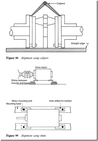
Calipers and straight edge
1 Place a straight edge on the flange rims at the top and sides (Figure 98).
When the coupling is in alignment, the straight edge should rest in full contact upon the flange rims.
Check the dimension with inside calipers on at least four points of the circumference of the flanges. If these dimensions are within 0.39 mm 64 inch) of each other, the alignment is satisfactory. Refer to the manu- facturer’s instructions if available.
3 Move the equipment and repeat steps 1 and 2 if necessary.
4 Tighten all bolts. Recheck tightness after several hours operation.
Appearance
When the coupling is in correct alignment, both laminated ring assemblies will be in a perfect plane at right angles to the shaft centre line.
When the equipment is operating at full speed, both laminated rings should have a distinct and clearly defined appearance when viewed from both the top
and the side. Should they have a blurred appearance, the coupling needs to be realigned.
Mounting
During the coupling alignment it may be necessary to raise the level of the drive shaft to coincide with that of the compressor shaft. This can be achieved by placing shims (Figure 99) beneath the motor mounts; the shims are holed for location of motor mounting bolts. It will then be necessary to conduct a parallel alignment test several hours after the equipment has been operating in case the shims have bedded down, thereby putting the coupling out of alignment.
When a coupling has been correctly aligned and operated satisfactorily, holes should be drilled through the motor mounts and mounting base. These can be either tapped to receive a bolt or left untapped for insertion of a dowel pin. Securing will ensure that no angular movement of the driver shaft is possible.
