Stress of Converter Imposed by Wind Speeds
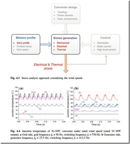
The wind speed decides the amount of active power generated by the wind turbines and as well the loading level of wind power converter. In this section, the electrical and thermal stress of converter imposed by the wind speeds are going to be investigated. The relevant approach for the stress analysis is highlighted in Fig. 4.3. It is noted that in order to establish a proper operating condition for analysis, all of the three factors (i.e., mission profile, converter design, and converter control) need to be involved and they also have impacts to the stresses of converter. However, only the stresses imposed by the mission profile (in this case wind speed) are going to be focused in this section.
Thermal Stress Under Steady-State Wind Speeds
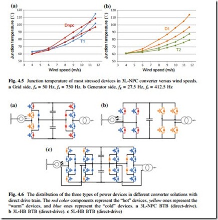
A. Thermal Lading of 3L-NPC Converter Under Diffident Wind Speeds Figure 4.4 shows the junction temperature of the given 3L-NPC converter under rated wind speed with 10 MW output, where the temperature distributions of power devices in both the generator side and grid-side converters are presented. Figure 4.5 shows the junction temperature profiles of the 3L-NPC converter under different
wind speeds. It can be seen that the thermal stress in the converter is quite unequal not only among different power devices, but also between generator side and grid side. On the grid side, the clamping diode Dnpc and outer switch T1 are the hottest devices with much higher junction temperature level compared to other devices— that means shorter life time to failure according to Fig. 4.12. On the generator side, the freewheeling diodes D1 become the most stressed device.
The thermal stress profile under various wind speeds can be used as an insight indicator for the loading level of power semiconductor devices, and the clues about how to optimize the device ratings and heat sink are thereby located. The thermal
profile under different wind speeds in Fig. 4.5 can be also used as a lookup table to estimate the lifetime of power devices subjected to long-term variations of wind speeds. The detailed analysis and results can be found in [18].
B. Device Utilization of Different Topologies
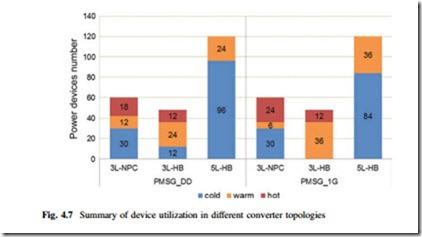
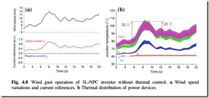
With the information of thermal stress under rated wind speed, the loading map of different converter configurations can be obtained. As shown in Fig. 4.6, several multi-level topologies mentioned in Chap. 2 are indicated based on the same 10-MW wind turbine. According to the loading level, the power devices in different topologies can be categorized into three types: the “hot” devices which have the junction temperature above 105 °C, the “warm” devices which have the junction temperature between 70 and 105 °C, and “cold” devices which have the junction
temperature below 70 °C. It can be seen from Fig. 4.6 that the “week point” or “hot spot” of a certain converter topology can be clearly indicated [7].
The numbers of the three types of power devices in different converters are summarized in Fig. 4.7, where situation with the direct-drive-train is indicated. The proportion of the three types of power devices will be a useful tool to indicate the information of device utilization and reliability for a certain converter solution: The more “cold” devices a converter has, the less sufficient utilizing of the power devices; some of the IGCTs or diodes could be barely used. The more “warm” devices a converter has, the more sufficient use of the power devices; this will be the ideal operating condition when designing a converter. While the more “hot” devices a converter has, the more over-loading of the power devices, the heat sink or device capacity may be under-designed. It can be seen that the given 5L-HB, 3L-HB converter topologies in [7] may reduce the numbers of the “hot” devices, achieving more equal device utilization compared to the 3L-NPC topology.
Thermal Stress Under Wind Speed Variations
During wind speed variations, the mechanical parts, electric-machine, and power electronics converter all suffer from loading fluctuations. The excursion of the thermal stress may quickly trigger many failure mechanisms in power semicon- ductors and result in significantly reduced life time of the converter. Therefore, different from the stress analysis under steady-state wind speed, the thermal excursion in power devices is more focused under the wind speed variations.
By the wind speed models presented in [19] and Sect. 7.1, a wind speed variation is generated in Fig. 4.8a, which fluctuates between 7.5 and 12 m/s within 20 s. According to the turbine and machine models presented in Sect. 7.1, this wind
speed variations can be transferred to the corresponding current references for the grid-side converter, as also indicated in Fig. 4.8. It is noted that the reactive current Iq delivered by the grid-side converter is normally set to be zero if the amplitude of grid voltage is within normal range.
The junction temperature of the power devices in the given 3L-NPC grid-side converter is shown in Fig. 4.8b, which is the thermal response to the predefined wind speed variation and corresponding current references in Fig. 4.8a. It can be seen that the clamping diode Dnpc and outer switch Tout suffer from the highest thermal stress as well as the excursion amplitude; this is the adverse loading condition from the point view of device lifetime as claimed before.


