This chapter gives the stress analysis of wind power converter under normal operation based on a 10-MW wind turbine. The junction temperature profiles in the power semiconductors are first presented under both steady-state and variable wind speeds. Then the converter efficiency and thermal distribution modified by grid codes are also investigated. Finally, a thermal control concept which utilizes the reactive power circuited among paralleled converters is proposed to relieve the excursion of junction temperature under wind gust.
Requirements and Conditions Under Normal Operation
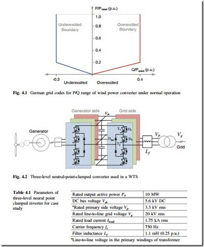
The normal operation is the most dominant status for a wind power converter. Under this operating mode, the wind turbine system is running between the designed cut-in and cut-out wind speeds, and the grid voltage is always maintained at rated value with an amplitude variation below 5 %. The wind power converter is normally injecting all the available power from wind turbines to the power grid, and the delivered reactive power should be restrained in a certain range depending on the active power output as well as countries. An example of German grid codes for offshore wind farm is shown again in Fig. 4.1, where the boundaries for under- excited and overexcited reactive powers delivered by the wind turbine system are both specified [1, 2].
As mentioned before, the three-level neutral-point-clamped (3L-NPC) topology seems to be a promising candidate for the next generation wind turbine system. This topology is chosen and basically designed for a 10-MW wind turbine as a case study in this chapter, as shown in Fig. 4.2, where the major design parameters for the converter system are summarized in Table 4.1 [3–8].
The converter is simulated under the PLECS Blockset in Simulink environment [9], and the detailed simulation condition is indicated as follows:
For the electrical simulation, the parameters of a 10-MW PMSG which are the same as Table 7.1 in Sect. 7.1 are used [10–12], and the generator side filter is not
taken into account. All of the power switching devices have the commutated voltage of 2.8 kV in order to utilize the available 4.5 kV high-power IGCT/IGBT on the market. The most commonly used carrier-based PD-PWM for 3L-NPC converter and the d/q frame power control method based on PI controller are applied [13, 14]. The equivalent switching frequency of converter is designed to be 750 Hz for the grid side and 412.5 Hz for the generator side (27.5 Hz fundamental frequency, direct driven) in order to get an acceptable switching loss in the power devices at 10-MW power conversion. The grid-side filter design for MW wind power converter has been comprehensively investigated in [15]; a filter inductance is considered in the simulation, and it is designed to limit the maximum current ripple to 25 % of the rated current amplitude. For simplicity and to focus the analysis on the device stress, the filter capacitance is not taken into account; the power grid is considered as three 20 kV/50 Hz ideal AC voltage sources; the resistance in the generator and the cables is not taken into account; DC bus capacitance is assumed high, and the transformers are assumed ideal.
For the loss and thermal simulation of power semiconductor devices, the press-pack IGCT 5SHY 40L4511 (4.5 kV/3.6 kA) and recommended diodes 5SDF 10H4503 are chosen [16, 17]. The thermal model for power devices is similar to Fig. 3.10, and each of the parameters for thermal impedance can be found from the manufacturer datasheets and Sect. 7.1. It is noted that the temperature of the heat sink TH is normally much lower and more stable compared to the junction temperature Tj in a properly designed converter system; therefore for simplicity the heat sink temperature is considered as an adverse and constant value at 60 °C. However, in the reality, the heat sink temperature may strongly depend on the operation environment and the design of the heat sink (air or liquid cooled).
