Engine mechanical
Engine malfunctions fall into four categories: fluid leaks, excessive oil consumption, loss of compression, and bearing wear.
Fuel leaks
External fuel leaks are discussed earlier in this chapter. Fuel contamination of the lube oil (as from failure of Roosa pump seals or HEUI injector o-rings) can be detected by the loss of viscosity and the telltale odor.
Oil leaks
In rough order of frequency, the most common sites of oil leaks are
• Valve cover gasket
• Oil pan gasket
• Timing case gasket
• Front and rear crankshaft seals
• Oil cooler
• Camshaft and oil gallery plugs
Tracing the source of a small leak can be difficult, because oil tends to migrate down and back, toward the rear of the engine. A black light detector or the aerosol powders sold for this purpose help, but the ultimate tactic is to pressurize the crankcase. Connect a low-pressure (5-psi maximum) air line to the dipstick tube. Soap the engine down and look for bubbles. Light foaming at valve cover gaskets is
permissible. The rope-type crankshaft seals used in older engines might leak air and still function when the engine runs; lip seals may foam, but should not hemorrhage.
Internal oil leaks past bearings shows up as a loss of pressure, a condition that should be verified with an accurate test gauge made up to the main oil gallery (Fig. 4-13). A pressure drop when loads are applied to a warm engine indicates excessive bearing clearances.
Oil enters the coolant by way of leaks in oil cooler or, more rarely, head gas- ket. Pressure test the cooler as described in Chap. 8, “Lubrication systems”; the head must be removed to detect leaks across the gasket, which makes the exercise a bit redundant.
The lower, external oil seal on HEUI injectors is all that stands between high- pressure lube oil and the fuel supply. A leak here can empty the sump within a few miles of driving. See Chap. 6 for more information.
Coolant leaks
External leaks are usually visible; identifying internal coolant leak paths requires some detective work. Massive leaks into the combustion chamber produce white smoke at normal engine temperatures. Such leaks can sometimes be seen as coolant flow through the EGR valve.
A burst of steam when the dipstick is touched to a hot exhaust manifold signals the presence of water in the sump. Ethylene glycol coats the stick with brown varnish almost impossible to wipe off. Have the oil tested and, if the test shows the presence of antifreeze, prepare to tear the engine down for cleaning. Large accumulations of coolant in the sump convert the oil to a white, mayonnaise-like emulsion.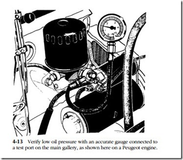
Excessive oil consumption
Blue smoke is the primary indicator of oil burning, although catalytic converters can disguise the condition. The question facing the mechanic is the source of the oil. Blue smoke at all speeds, hot or cold, points to cylinder/ring wear, which can be verified with tests described below. Smoke during acceleration after periods of idle and immediately upon startup indicates leaking valve seals. Oil in the intake mani- fold and/or air boxes originates from an upstream source, usually leaking turbo or blower seals. But other possibilities should not be overlooked. Sometimes merely changing the air filter element corrects the problem.
Loss of compression
Disabling one injector at a time will isolate any weak cylinders. If changing out the associated injectors does not restore power, the problem is almost surely com- pression-related. Loss of compression across all cylinders will be accompanied by high oil consumption and a noticeable reduction in power output.
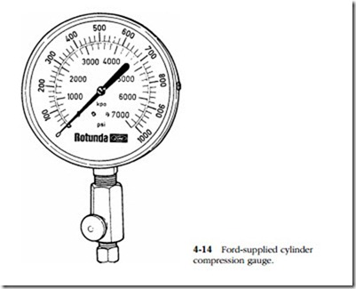
The cylinder compression gauge (Fig. 4-14) is an essential tool for diesel mechanics. Test procedures vary with make (e.g., some manufacturers specify a cold reading, while others require that the engine be at normal operating temperature). But the general procedure is as follows:
1. Cut off the fuel supply or disconnect the camshaft position sensor on com- puterized engines. Otherwise, the cylinder under test can fire and destroy the gauge.
2. Disable all cylinders by (depending upon how the gauge is mounted) removing the glow plugs or injectors.
3. Test each cylinder in turn, allowing about six compression strokes per gauge reading.
4. Check the readings against published specifications and against each other.
Variations of 20% or more between cylinders results in noticeable roughness.
WARNING: do not squirt oil into the cylinder in an attempt to determine if the compression loss is due to rings or valves. The cylinder might fire.
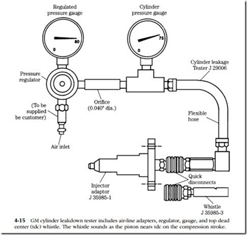
Figure 4-15 illustrates a GM leakdown test kit with glow-plug adapter. Unlike competitive testers, the unit does not measure leakdown percentage, but it does indi- cate the source of air leaks, which is the purpose of the exercise.
1. Remove the radiator cap and warm the engine to operating temperature.
2. Shut off the engine and, using the timing marks, position No. 1 cylinder at top dead center (tdc). Finding tdc for the remaining cylinders is a bit challenging, but can be accomplished with a degree wheel or with the help of the whistle supplied with the kit.
WARNING: if a piston is not at or very close to tdc, the engine will “motor,” catching a hapless mechanic in the fan or belts.
3. Install the tester and apply about 75 psi of compressed air to it.
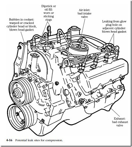
4. The significance of the various leak sites is listed in Fig. 4-16.
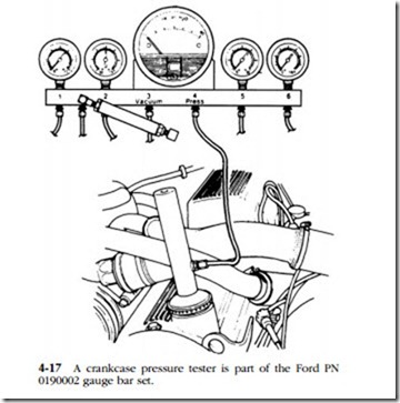
The amount of blowby past the rings is a rough indicator of cylinder bore/ring wear. Figure 4-17 illustrates the test apparatus, consisting of a pressure gauge and an adaptor that replaces the oil filler cap. PCV atmospheric vents must be sealed. A major limitation of this test is that few manufacturers provide rpm/blowby pressure specifications. The mechanic must establish the norm while the engine is still healthy.
Oil analysis
Short of tearing the engine down for inspection, oil analysis is the best index of wear. The technology, developed initially for diesel locomotives and perfected by the U.S. Navy, can predict engine failure with some exactitude. The oil sample undergoes spectroscopic analysis to identify 16 or more elements with an accuracy of within one part per million. Bearing wear shows up as lead, silver, tin, and aluminum; liner and ring wear as iron and chromium; valve wear as nickel; and bushings as copper. Silicon and aluminum particles suggest air filter failure.
