Stress of Converter Imposed by Grid Codes
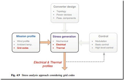
Besides the wind speeds, various grid requirements which have regulations for the active/reactive power delivery will also modify the loading of wind power converter. In this section, the electrical and thermal behaviors of the given 3L-NPC wind power converter imposed by the grid codes for normal operation are going to be investigated. The relevant stress generation process is highlighted in Fig. 4.9. It can be seen that this analysis also focuses on the estimation of electrical and thermal stresses considering the impacts by mission profile (in this case the grid codes), although other factors should be also involved in order to establish a proper operating condition for the converter.
Converter Efficiency Considering Reactive Power Demands by Grid Codes As mentioned in Chap. 1, the reactive power ranges delivered by wind power converter at different active power outputs have to be regulated by grid codes in a
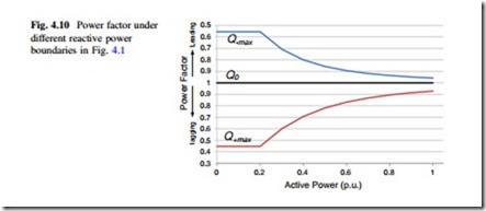
certain range. The German grid codes are used here as an example, and the corresponding ranges of power factors are plotted in Fig. 4.10 according to Fig. 4.1. The enormously modified power factors under different active power outputs may change the loss distribution of power devices and lead to unexpected efficiency performances of the grid-side converter.
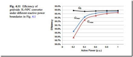
The efficiency of the given 3L-NPC grid-side converter under different active power outputs is shown in Fig. 4.11, in which the conditions of the three extreme power factors in Fig. 4.10 are indicated. It is noted that the loss in the clamping circuits and filters are not taken into account. As it can be seen, the converter efficiency may be much lower than expected when considering the grid
requirements for the reactive power under normal operation, and this should be taken into account when evaluating and designing the wind turbine system. The similar efficiency performances of a 5L-MLC2 multi-level converter considering grid codes can be found in [20].
4.3.2 Thermal Stress Considering Reactive Power Demands by Grid Codes
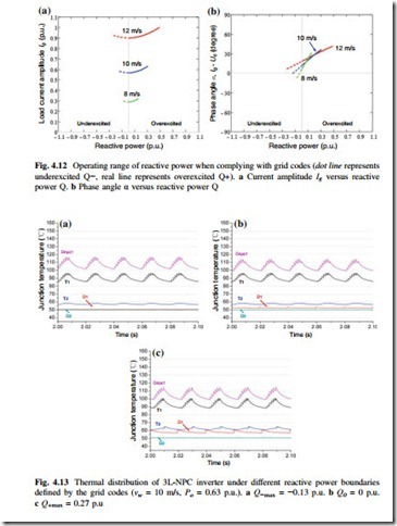
In order to investigate the thermal stress imposed by grid codes, the converter’s electrical behaviors modified by the grid requirements have to be clarified. The current amplitude and phase angle of converter with relation to the allowable reactive power range defined by German grid codes are plotted in Fig. 4.12a, b, respectively, in which the situations when the wind speed is 12 m/s (Po = 1 p.u.), 10 m/s (Po = 0.6 p.u.), and 8 m/s (Po = 0.3 p.u.) are indicated. It can be seen that when complying with grid codes, the delivered active/reactive power by the wind power converter is restrained in a narrow range which is much smaller than the capability of the converter.
The corresponding junction temperature of the 3L-NPC converter is shown in Fig. 4.13, where the wind turbine is generating 0.63 p.u. active power at 10 m/s wind speed and three extreme reactive power conditions required by grid codes are applied: (a) maximum underexcited reactive power when Q−max (10 m/s) = −0.13 p.u.,
(b) no reactive power when PF = 1, and (c) maximum overexcited reactive power
when Q+max (10 m/s) = 0.27 p.u.
It can be seen that when complying with the regulations by grid codes, the thermal loading in the most stressed devices (Dnpc and T1) has no significant difference among the three extreme reactive power conditions. More detailed analysis and function regarding the electrical and loss behaviors modified by reactive power can be found in the special attached topic 11.


