High-voltage (transmission) switchgear
System considerations
The transmission of high powers over long distances necessitates the use of High (HV), Extra High (EHV) or Ultra High (UHV) voltages. Historically, these voltages were classed as 72.5kV and above. The lower voltages were introduced first, and as the technologies have developed these have increased so that now the highest transmission volt- ages being used are 1100 kV. For long transmission distances it is also possible to use DC systems; these have particular advantages when two systems are to be connected, but they are beyond the scope of this section, which considers only ac transmission switchgear.
In UK the 132 kV system was first established in 1932, and subsequent growth has required expansion of the system up to 275 kV (1955) and 420 kV (1965). Other countries
have developed similarly, so a multiple voltage transmission system exists in virtually every major electricity-using nation.
In recent years there has been some harmonization of the rated voltages of transmission systems, the agreed levels set down in IEC 694 being 72.5 kV, 100 kV, 123 kV, 145 kV, 170 kV, 245 kV, 300 kV, 362 kV, 420 kV, 550 kV and 800 kV. Systems will be operated at a variety of normal voltage levels such as 66 kV, 132 kV, 275 kV and 400 kV, but the maximum system operating voltage may be higher than these nominal ratings, so the next highest standard value will be selected as the rated voltage of the system.
In order to connect, control and protect these transmission systems it is necessary to use switchgear of various types and ratings.
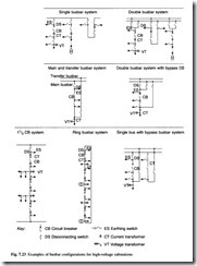
A switchgear installation which allows the connection and disconnection of the interconnecting parts of a transmission system is referred to as a substation. A substation will include not only the switchgear, but also transformers and the connections to overhead lines or cable circuits. The main functional elements of the switchgear installation in a substation are circuit breakers, switches, disconnectors and earthing switches. Some of the most common configurations for substations are illustrated in Fig. 7.23.
Switching conditions on transmission systems are similar in principle to those on distribution systems, with a requirement to interrupt normal load currents, fault currents and to undertake off-load operations. Because of the different circuit parameters in transmission and distribution networks, the switching duties impose particular requirements which have to be taken into account during the design and type testing of switchgear equipment. A particular requirement for transmission is the ability to deal with the onerous transient recovery voltages which are generated during interruption of faults on overhead lines when the position of the fault is close to the circuit breaker terminals; this is defined in IEC 62271-100 as the Short Line Fault condition. A further requirement is the energization of long overhead lines, which can generate large transient overvoltages on the system unless counter-measures are taken.
Types of circuit breaker
The first designs of transmission circuit breaker used minimum-volume oil interrupter technology similar to that which had been developed for distribution switchgear.
The 1940s saw the development and introduction of air-blast circuit breakers throughout the world. These devices used compressed air at pressures up to 1200 psi,
not only to separate the contacts but also to cool and de-ionize the arc drawn between the contacts. Early air-blast designs used interrupters which were not permanently pressurized, and reclosed when the blast was shut off. Isolation was achieved sepa- rately by a series-connected switch which interrupted any residual resistive and/or capacitive grading current, and had the full rated fault-making capacity.
The increase of system voltages to 400 kV in the late 1950s coincided with the discovery, investigation and specification of the kilometric or short line fault condition. Air-blast interrupters are particularly susceptible to high Rates of Rise of Recovery Voltage (RRRV), and parallel-connected resistors are needed to assist interruption. At the increased short-circuit current levels of up to 60 kA which were now required, parallel resistors of up to a few hundred ohms per phase were required, and the duty of breaking the resistor current could no longer be left to the series-connected air switch. To deal with this, permanently pressurized interruptors incorporating parallel- resistor switching contacts were used. The original pressurized-head circuit breakers used multiple interrupters per phase in order to achieve the required fault-switching capacity at high transmission voltages; 10 or 12 interrupters were used for 400 kV. These were proved by direct unit testing at short-circuit testing stations, each having a direct output of 3 GVA. It was in fact the ability to test which determined the number of interrupters used in the design of a circuit breaker.
The introduction of synthetic testing methods increased the effective capacity of short-circuit testing stations by an order of magnitude, and this allowed the proving of circuit breakers having fewer interrupters. So, 400 kV air-blast circuit breakers with only four or six interrupters per phase were being supplied and installed up to the late 1970s.
The next step-change in technology occurred with the introduction of SF6 circuit breakers. The merits of electronegative gases such as SF6 had long been recognized, and freon had been used in the late 1930s to provide the primary insulating medium in 33 kV metalclad switchgear installed in two UK power stations. The reliability of seals was a problem, and it was only during the nuclear reactor programme that sufficiently reliable gas seals were developed to enable gas-insulated equipment to be reconsidered.
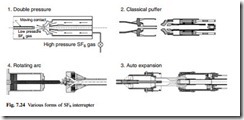
The first practical application of SF6 in switchgear was as an insulating medium for instrument transformers in transmission substations in the late 1950s and early 1960s. These were quickly followed by the use of SF6 not only as an insulating medium but also as the means of extinguishing arcs in circuit breakers. The first generation of SF6 circuit breakers were double-pressure devices which were based on air-blast designs, but using the advantages of SF6. These double-pressure designs were quickly followed by puffer circuit breakers which have already been described in section 7.4.1. Puffer circuit breakers, now in the form of second or third generation of development, form the basis of most present-day transmission circuit breaker designs. Figure 7.24 illustrates the various forms of SF6 interrupter.
Main classes of equipment
Transmission substations may be built indoors or outdoors but because of the space required it is usually difficult to justify an indoor substation. The strongest justification for an indoor substation is the effect of harsh environments on the design, operation and maintenance of the equipment.
The two main types of transmission switchgear currently available are conventional or Air-Insulated Switchgear (AIS) and gas-insulated metal-enclosed switchgear.
Conventional or Air-Insulated Switchgear (AIS)
Here the primary insulating medium is atmospheric air, and in the majority of AIS the insulating elements are of either solid or hollow porcelain.
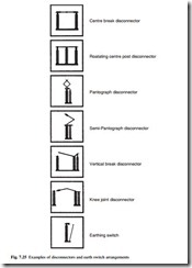
In circuit elements such as disconnectors and earthing switches, where the switch- ing is done in air, the insulators are solid, and provide not only physical support and insulation, but also the mechanical drive for the elements. Examples of disconnectors and earth switch arrangements are shown in Fig. 7.25. The choice of disconnector design is dependent on the substation layout and performance requirements.
Equipment such as circuit breakers which need an additional insulating or inter- rupting medium use hollow porcelain insulators which contain the active circuit elements in the appropriate insulating medium. As previously outlined, initial AIS installations used oil as the insulating and interrupting medium, which in many cases was replaced by the use of compressed air, and modern designs almost always use SF6 gas.
The layout of a substation is governed by the need to ensure that air clearances meet the dielectric design requirements, including conditions when access is required to the substation for maintenance. Rules for the minimum clearances and the requirements for creepage distances on the external porcelain insulators are contained in the standards. For locations with atmospheric pollution, it is necessary to provide extended creepage distances on insulators. Guidelines for the selection of creepage distance are given in IEC 815.
A recent development in AIS technology is the use of composite insulators for functional elements in place of the traditional porcelain. There is a risk of explosion with porcelain insulators when they are filled with insulating gas if a mechanical fault occurs with the equipment. A composite insulator consists of silicone rubber sheds on a filament glass-fibre tube; it is not brittle and will not explode if the insulator is ruptured. Composite insulators are now being used on instrument transformers and circuit breakers for AIS, and their use is likely to become more common.
An example of an outdoor AIS substation is shown in Fig. 7.26.
Gas-insulated metal-enclosed switchgear
In metal-enclosed switchgear there is a an external metal enclosure which is intended to be earthed; it is complete except for external connections. The earliest transmission metal-enclosed equipment used oil as the insulating medium, but since the introduction of SF6, all transmission metal-enclosed switchgear is based on SF6 as the insulating medium.
The main significance of the Gas-Insulated Substation (GIS) principle is the dramatic reduction of insulating clearances made possible by SF6, resulting in much more compact substation layouts. GIS are easier and more economic to accommodate where land use is critical, such as in many urban areas. It also offers considerable advantages in applications where environmental pollution is severe, such as in coastal,
desert or heavily industrialized areas. Environmental conditions can also influence the need for maintenance of the switchgear and the implementation of that maintenance; GIS is so compact that transmission substations can be indoor, reducing the maintenance problems considerably. The greater reliability of GIS is another factor which is encouraging its increased application.
GIS switchgear is generally of modular design. All individual elements such as busbars, disconnectors, instrument transformers and circuit breakers are contained in interconnecting earthed enclosures filled with SF6 at up to 7 bar. At the highest volt- age levels, the three phases are housed in separate phase-segregated enclosures. At the lower voltages it is common for all three phases to be housed in the same enclosure and with some designs this philosophy is extended up to 300 kV. Because of the possibility of heating effects from induced currents it is normal for phase-segregated designs to use non-magnetic materials (typically aluminium) for the enclosures, but for phase-integrated designs it is possible to use magnetic steels for some ratings without overheating constraints.
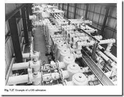
An example of a GIS substation is shown in Fig. 7.27.
Hybrid substations
A substation where there is a mix of GIS and AIS technologies is often referred to as a hybrid substation. This can be a substation that consists of bays where some are of AIS components only and some are a mix of AIS and GIS technology, or where some are of GIS components only. Alternatively, and more commonly, elements of AIS and GIS technology are typically mixed in the same bay of equipment and this mixture is a hybrid of the two technologies and is applied across the complete substation.
There are exceptions to this definition:
● if the only component in a GIS substation utilizing AIS technology is the inter- face connection (bushing or cable termination) to overhead line, cable or trans- former, the substation is still considered as a GIS substation
● in an AIS substation where only one component is provided in GIS technology, or where additional elements have a mixture of air and gas insulation but the primary insulation to earth is still air (as in a dead tank arrangement) then these substations are still considered as AIS
Any other combinations are considered as hybrid, for instance where only busbars are SF6 insulated, or where an enclosed gas-insulated circuit breaker contains additional equipment such as instrument transformers or earthing switches.
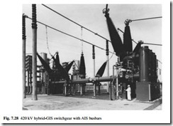
An example of a hybrid substation is shown in Fig. 7.28.
Rating principles
As for distribution switchgear, the main consideration in the choice of rating for a particular system is the rated normal current and the rated short-circuit current. Power system studies using load flow and transient analysis techniques will establish the values of the parameters for individual systems. It is also necessary to select lightning impulse rated values from the range of standard values specified in standards (as for distribution switchgear) and to specify for transmission systems with a rated voltage of 300 kV and above a rated switching impulse withstand voltage. The rated switching surge voltage level is defined as the peak voltage of a unipolar standard
250/2500 µs waveform; this represents the transient voltages which are generated by the operation of circuit breakers when switching overhead lines, shunt reactors and other circuits.
An important consideration in the choice of equipment ratings for transmission systems is insulation co-ordination. Insulation co-ordination is the selection of the electric strength of equipment and its application in relation to the voltages which can appear on the system taking into account the characteristics of any protective devices, so as to reduce to an economically and operationally acceptable level the probability that the resulting voltage stresses imposed on the equipment will cause damage to the equipment or affect continuity of service. For system voltages up to 300 kV, experience has demonstrated that the most important factor in determining system design is the stress due to lightning; for voltages over 300 kV the switching over-voltage increases in importance. It is now common to use Metal Oxide surge Arrestors (MOA) to limit lightning over-voltage levels on transmission systems. In addition, the MOA can in many cases provide adequate limitation of switching over-voltages, but for longer overhead lines it may be required to use a circuit breaker with controlled (or point-on- wave) switching in order to keep over-voltages at acceptable levels. The traditional technique of using circuit breakers with parallel pre-insertion resistors is now being replaced by the use of the MOA and controlled switching.
Test methods
International standards require that switchgear must be so designed and manufactured that it satisfies test specifications with regard to its insulating capacity, switching performance, protection against contact, current-carrying capacity and mechanical function. Evidence of this is obtained by type testing a prototype or sample of the switchgear. In addition, routine tests are performed on each individual item of switchgear manufactured, either on completed or sub-assembled units in the factory or on site.
Type tests are performed on transmission switchgear in a similar manner to those applied to distribution switchgear (see section 7.4.4), but because of the difference in rated values, the necessary test values, the test equipment and techniques differ in detail. Some tests which are specific to transmission switchgear are as follows:
● dielectric tests. In addition to lightning impulse and power frequency tests it is necessary to perform switching impulse tests for equipment with a rated voltage above 300 kV.
● short-circuit and switching tests. The test parameters for transmission equipment involve much higher energy requirements than for distribution equipment, so special techniques have been developed over the years. To provide the high voltage and high currents needed for transmission switchgear, it is usual to provide a ‘synthetic’ test source where the high voltage and high currents are provided in the same test from different sources.
Routine tests are performed on all switchgear units or sub-assemblies to ensure that the performance of the factory-built unit will match that of the type-tested unit. The AIS is normally fully assembled in the factory and routine tested as a complete functioning unit. Routine tests will include mechanical operations to check operating characteristics, resistance checks of current-carrying paths, tests on control and auxiliary circuits and power-frequency withstand tests to verify insulation quality. For GIS, particularly at higher voltage levels, it is not practical to assemble fully a complete installation in the factory. Therefore sub-assemblies of GIS or transportable assemblies are individually tested prior to shipment; for GIS at 145 kV or 245 kV this might involve a complete ‘bay’ or circuit of equipment, but at 420 kV or 550 kV the size of the equipment dictates that only sub-assemblies can be transported to site as a unit. Tests on transportable assemblies include power-frequency withstand with partial dis- charge detection, verification of gas tightness, mechanical operations and main circuit resistance.
Commissioning and maintenance
Due to the size of transmission switchgear it is necessary to transport the equipment to site in sub-assemblies and then to re-assemble to complete switchgear on site. This procedure is more extensive than for distribution switchgear and it results in more elaborate commissioning tests.
After routine testing at the factory, AIS is dismantled into sub-assemblies for transport to site and then re-assembled at the substation. A short series of operational and functional checks are performed before the equipment is put into service.
Site commissioning procedures for GIS are more elaborate than for AIS, since GIS can be particularly sensitive to assembly defects or to particulate contamination; because of the small electrical clearances made possible by SF6, it is essential that all particulate contamination down to the size of about 1 mm is excluded from the equipment. For these reasons extensive power-frequency withstand tests are performed on site on the completed installation. The requirements for commissioning of GIS are covered in IEC 62271-203.
Modern designs of transmission switchgear are becoming simpler and inherently more reliable, with reduced maintenance requirements. The traditional preventive maintenance approach, with maintenance performed at prescribed intervals irrespective of the condition of the switchgear, is being replaced by predictive maintenance in
![]() which maintenance is needed only when the condition of the equipment warrants intervention or where operational duties are severe. Diagnostic techniques and condition monitoring to support this are now becoming available; in particular, it is very difficult to apply conventional partial discharge tests to a complete GIS installation and special diagnostic techniques have been developed to monitor its structural integrity.
which maintenance is needed only when the condition of the equipment warrants intervention or where operational duties are severe. Diagnostic techniques and condition monitoring to support this are now becoming available; in particular, it is very difficult to apply conventional partial discharge tests to a complete GIS installation and special diagnostic techniques have been developed to monitor its structural integrity.
Many items of transmission switchgear are still in service after 30, 40, or even 50 years of satisfactory service. A typical design life for modern transmission switchgear is 40 years, but this is conservative in comparison with the figures being achieved on the older equipment still in service today.
Standards
Some of the commonly used standards and specifications for transmission switchgear are given in Table 7.6.
