Impedances
3.4.1 Resistance
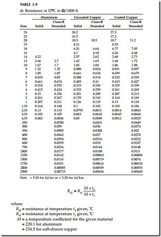
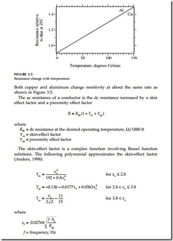
Cable conductor resistance is an important part of impedance that is used for fault studies and load flow studies. Resistance also greatly impacts a cable’s ampacity. The major variable that affects resistance is the conductor’s temperature; resistance rises with temperature. Magnetic fields from alternating currents also reduce a conductor’s resistance relative to its dc resistance. At power frequencies, skin effect is only apparent for large conductors and proximity effect only occurs for conductors in very tight configurations. The starting point for resistance calculations is the dc resistance. From there, we can adjust for temperature and for frequency effects. Table 3.9 shows the dc resistances of several common conductors used for cables.
Resistance increases with temperature as
ks = skin effect constant = 1 for typical conductors in extruded cables, may be less than one for paper cables that are dried and impregnated and especially those with round segmental conductors [see Neher and McGrath (1957) or IEC (1982)].
Rdc = dc resistance at the desired operating temperature, W/1000 ft For virtually all applications at power frequency, xs is < 2.8.
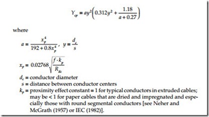
With a conductor in close proximity to another current-carrying conductor, the magnetic fields from the adjacent conductor force current to flow in the portions of the conductor most distant from the adjacent conductor (with both conductors carrying current in the same direction). This magnetic field effect increases the effective ac resistance. The proximity effect factor is approximately (Anders, 1998; IEC 287, 1982):
At power frequencies, we can ignore proximity effect if the spacing exceeds ten times the conductor diameter (the effect is less than 1%).
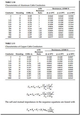
Table 3.10 and Table 3.11 show characteristics of common cable conductors.
Impedance Formulas
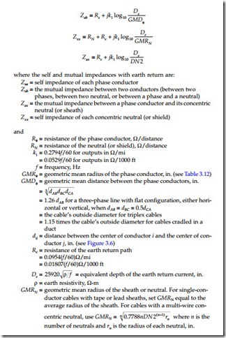
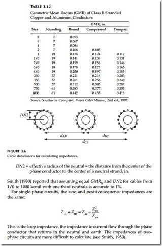
Smith and Barger (1972) showed that we can treat a multi-wire concentric neutral as a uniform sheath; further work by Lewis and Allen (1978) and by Lewis, Allen, and Wang (1978) simplified the calculation of the representa- tion of the concentric neutral. Following the procedure and nomenclature of Smith (1980) and Lewis and Allen (1978), we can find a cable’s sequence impedances from the self and mutual impedances of the cable phase and neutral conductors as
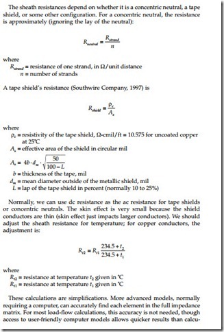
The sheath resistances depend on whether it is a concentric neutral, a tape shield, or some other configuration. For a concentric neutral, the resistance is approximately (ignoring the lay of the neutral):
lating the equations shown here. For evaluating switching transients and some ampacity problems or configurations with several cables, we some- times need more sophisticated models [see Amateni (1980) or Dommel (1986) for analytical details].
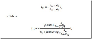
In a cable, the neutral tightly couples with the phase. Phase current induces neutral voltages that force circulating current in the neutrals. With balanced, positive-sequence current in the three phases and with symmetrical conduc- tors, the neutral current (Lewis and Allen, 1978; Smith and Barger, 1972) is
Since DN2 and GMRN are almost equal, if RN is near zero, the neutral (or shield) current (IX1) almost equals the phase current (Ia). Higher neutral resistances actually reduce positive-sequence resistances.
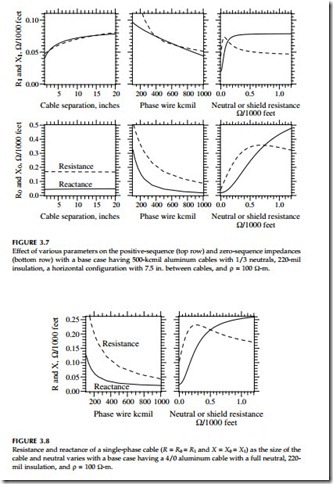
Significant effects on positive and zero-sequence impedances include:
• Cable separation — Larger separations increase Z1; spacing does not affect Z0. Triplex cables have the lowest positive-sequence impedance.
• Conductor size — Larger conductors have much less resistance; reac- tance drops somewhat with increasing size.
• Neutral/shield resistance — Increasing the neutral resistance increases the reactive portion of the positive and zero-sequence impedances. Beyond a certain point, increasing neutral resistances decreases the resistive portion of Z1 and Z0.
• Other cables or ground wires — Adding another grounded wire nearby has similar impacts to lowering sheath resistances. Zero-sequence resistance and reactance usually drop. Positive-sequence reactance is likely to decrease, but positive-sequence resistance may increase.
Figure 3.7 and Figure 3.8 show the impact of the most significant variables on impedances for three-phase and single-phase circuits. None of the following significantly impacts either the positive or zero-sequence imped- ances: insulation thickness, insulation type, depth of burial, and earth resistivity.
Impedance Tables
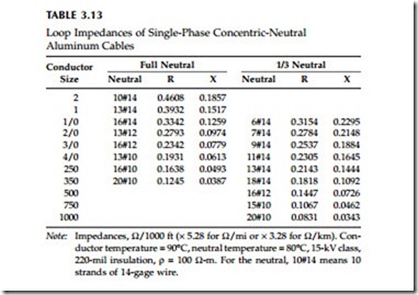
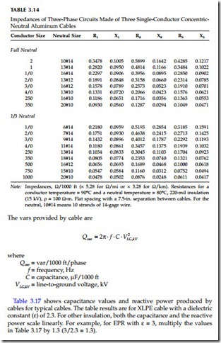
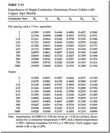
This section contains tables of several common cable configurations found on distribution circuits. All values are for a multigrounded circuit. Many other cable configurations are possible, with widely varying impedances. For PILC cables, refer to impedances in the Westinghouse (1950) T&D book. For additional three-phase power cable configurations, refer to the IEEE Red Book (IEEE Std. 141-1993), St. Pierre (2001), or Southwire Company (1997).
Capacitance
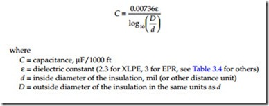
Cables have significant capacitance, much more than overhead lines. A sin- gle-conductor cable has a capacitance given by:
![]() Note: Impedances, W/1000 ft (´ 5.28 for W/mi or ´ 3.28 for W/km). Resis- tances for a conductor temperature = 90°C and a shield temperature
Note: Impedances, W/1000 ft (´ 5.28 for W/mi or ´ 3.28 for W/km). Resis- tances for a conductor temperature = 90°C and a shield temperature
= 50°C, 220-mil insulation (15 kV), r = 100 W-m, 5-mil copper tape shield with a lap of 20%.
