Voltage regulation
Most alternator-based charging circuits employ voltage regulation (as opposed to voltage and current regulation). The regulator can be external to the alternator or integral with it. External regulators can be mechanical or solid state.
External regulators
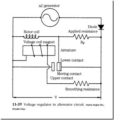
Figure 11-39 is a schematic of a typical mechanical voltage regulator. The voltage-sensing winding is in parallel with the output and drives NC (normally closed) contacts. As the generator comes up to speed, voltage increases until the winding develops a strong enough field to open the contacts. Rotor output then passes through dropping resistor RF.
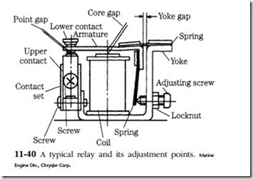
Depending on the make and model, voltage adjustment is accomplished by bending the stationary contact, moving the hinges in elongated mounting holes, or by screw (Fig. 11-40). In theory, the correct point gap should correspond with an output voltage of approximately 15V at 68°F or 28V for 24V systems. In practice, better results are had by measuring alternator output voltage at the battery terminals. Assuming that specifications are available, core and yoke gap adjustments also can be made.
Clean oxidized contacts with a riffle file or a diamond-faced abrasive strip. Do not use sandpaper or emery cloth. Inspect the dropping resistor (often found on the underside of the unit), springs, and contact tips for evidence of overheating. Check the regulator ground connection.
Before discarding a defective regulator, attempt to discover why it failed. Burnt points or heat-discolored springs mean high resistance in the charging circuit or a bad regulator ground.

