Much new distribution is underground. Underground distribution is much more hidden from view than overhead circuits, and is more reliable. Cables, connectors, and installation equipment have advanced considerably in the last quarter of the 20th century, making underground distribution installations faster and less expensive.
Applications
One of the main applications of underground circuits is for underground residential distribution (URD), underground branches or loops supplying residential neighborhoods. Utilities also use underground construction for substation exits and drops to padmounted transformers serving industrial or commercial customers. Other uses are crossings: river crossings, highway crossings, or transmission line crossings. All-underground construction — widely used for decades in cities — now appears in more places.
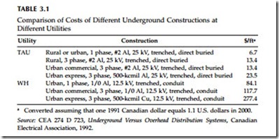
Underground construction is expensive, and costs vary widely. Table 3.1 shows extracts from one survey of costs done by the CEA; the two utilities highlighted differ by a factor of ten. The main factors that influence under- ground costs are:
• Degree of development — Roads, driveways, sidewalks, and water pipes
— these and other obstacles slow construction and increase costs.
• Soil condition — Rocks and frozen ground increase overtime pay for cable crews.
• Urban, suburban, or rural — Urban construction is more difficult not only because of concrete, but also because of traffic. Rural construc- tion is generally the least expensive per length, but lengths are long.
• Conduit — Concrete-encased ducts cost more than direct-buried con- duits, which cost more than preassembled flexible conduit, which cost more than directly buried cable with no conduits.
• Cable size and materials — The actual cable cost is a relatively small part of many underground applications. A 1/0 aluminum full-neu- tral 220-mil TR-XLPE cable costs just under $2 per ft; with a 500- kcmil conductor and a one-third neutral, the cable costs just under $4 per ft.
• Installation equipment — Bigger machines and machines more appro- priate for the surface and soil conditions ease installations.
Underground Residential Distribution (URD)
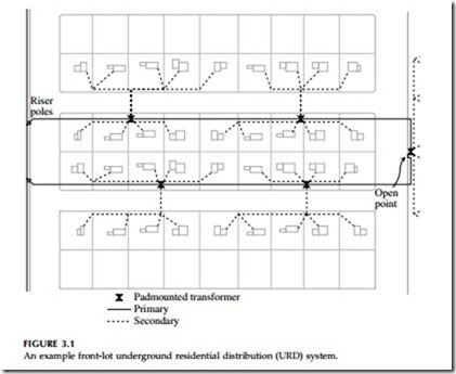
A classic underground residential distribution circuit is an underground circuit in a loop arrangement fed at each end from an overhead circuit (see Figure 3.1). The loop arrangement allows utilities to restore customers more quickly; after crews find the faulted section, they can reconfigure the loop and isolate any failed section of cable. This returns power to all customers. Crews can delay replacing or fixing the cable until a more convenient time or when suitable equipment arrives. Not all URD is con- figured in a loop. Utilities sometimes use purely radial circuits or circuits with radial taps or branches.
Padmounted transformers step voltage down for delivery to customers and provide a sectionalizing point. The elbow connectors on the cables (pistol grips) attach to bushings on the transformer to maintain a dead-front — no exposed, energized conductors. To open a section of cable, crews can simply pull an elbow off of the transformer bushing and place it on a parking stand, which is an elbow bushing meant for holding an energized elbow connector. Elbows and other terminations are available with continuous-current rat- ings of 200 or 600 A (IEEE Std. 386-1995). Load-break elbows are designed to break load; these are only available in 200-A ratings. Without load-break capability, crews should of course only disconnect the elbow if the cable is deenergized. Elbows normally have a test point where crews can check if
the cable is live. Elbows are also tested to withstand ten cycles of fault current, with 200-A elbows tested at 10 kA and 600-A elbows tested at 25 kA (IEEE Std. 386-1995).
The interface between the overhead circuit and the URD circuit is the riser pole. At the riser pole (or a dip pole or simply a dip), cable terminations provide the interface between the insulated cable and the bare overhead conductors. These pothead terminations grade the insulation to prevent excessive electrical stress on the insulation. Potheads also keep water from entering the cable, which is critical for cable reliability. Also at the riser pole are expulsion fuses, normally in cutouts. Areas with high short-circuit cur- rent may also have current-limiting fuses. To keep lightning surges from damaging the cable, the riser pole should have arresters right across the pothead with as little lead length as possible.
Underground designs for residential developments expanded dramatically in the 1970s. Political pressure coupled with technology improvements were the driving forces behind underground distribution. The main devel- opments — direct-buried cables and padmounted transformers having load- break elbows — dramatically reduced the cost of underground distribution to close to that of overhead construction. In addition to improving the visual landscape, underground construction improves reliability. Underground res-
idential distribution has had difficulties, especially high cable failure rates. In the late 1960s and early 1970s, given the durability of plastics, the poly- ethylene cables installed at that time were thought to have a life of at least 50 years. In practice, cables failed at a much higher rate than expected, enough so that many utilities had to replace large amounts of this cable.
According to Boucher (1991), 72% of utilities use front-lot designs for URD. With easier access and fewer trees and brush to clear, crews can more easily install cables along streets in the front of yards. Customers prefer rear-lot service, which hides padmounted transformers from view. Back-lot place- ment can ease siting issues and may be more economical if lots share rear property lines. But with rear-lot design, utility crews have more difficulty accessing cables and transformers for fault location, sectionalizing, and repair. Of those utilities surveyed by Boucher (1991), 85% charge for underground residential service, ranging from $200 to $1200 per lot (1991 dollars). Some
utilities charge by length, which ranges from $5.80 to $35.00 per ft.
Main Feeders
Whether urban, suburban, or even rural, all parts of a distribution circuit can be underground, including the main feeder. For reliability, utilities often configure an underground main feeder as a looped system with one or more tie points to other sources. Switching cabinets or junction boxes serve as tie points for tapping off lateral taps or branches to customers. These can be in handholes, padmounted enclosures, or pedestals above ground. Three-phase circuits can also be arranged much like URD with sections of cable run between three-phase padmounted transformers. As with URD, the pad- mounted transformers serve as switching stations.
Although short, many feeders have an important underground section — the substation exit. Underground substation exits make substations easier to design and improve the aesthetics of the substation. Because they are at the substation, the source of a radial circuit, substation exits are critical for reliability. In addition, the loading on the circuit is higher at the substation exit than anywhere else; the substation exit may limit the entire circuit’s ampacity. Substation exits are not the place to cut corners. Some strategies to reduce the risks of failures or to speed recovery are: concrete- enclosed ducts to help protect cables, spare cables, overrated cables, and good surge protection.
While not as critical as substation exits, utilities use similar three-phase underground dips to cross large highways or rivers or other obstacles. These are designed in much the same way as substation exits.
Urban Systems
Underground distribution has reliably supplied urban systems since the early 1900s. Cables are normally installed in concrete-encased duct banks beneath streets, sidewalks, or alleys. A duct bank is a group of parallel ducts, usually with four to nine ducts but often many more. Ducts may be precast concrete sections or PVC encased in concrete. Duct banks carry both primary and secondary cables. Manholes every few hundred feet provide access to cables. Transformers are in vaults or in the basements of large buildings.
Paper-insulated lead-covered (PILC) cables dominated urban applications until the late 20th century. Although a few utilities still install PILC, most use extruded cable for underground applications. In urban applications, copper is more widely used than in suburban applications. Whether feeding secondary networks or other distribution configurations, urban circuits may be subjected to heavy loads.
“Vertical” distribution systems are necessary in very tall buildings. Medium-voltage cable strung up many floors feed transformers within a building. Submarine cables are good for this application since their protec- tive armor wire provides support when a cable is suspended for hundreds of feet.
Overhead vs. Underground
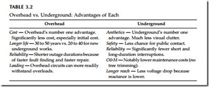
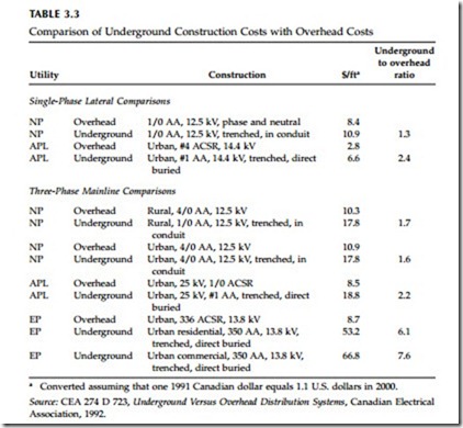
Overhead or underground? The debate continues. Both designs have advantages (see Table 3.2). The major advantage of overhead circuits is cost; an underground circuit typically costs anywhere from 1 to 2.5 times the equiv- alent overhead circuit (see Table 3.3). But the cost differences vary wildly, and it’s often difficult to define “equivalent” systems in terms of perfor- mance. Under the right conditions, some estimates of cost report that cable installations can be less expensive than overhead lines. If the soil is easy to dig, if the soil has few rocks, if the ground has no other obstacles like water pipes or telephone wires, then crews may be able to plow in cable faster and for less cost than an overhead circuit. In urban areas, underground is almost the only choice; too many circuits are needed, and above-ground space is too expensive or just not available. But urban duct-bank construction is expensive on a per-length basis (fortunately, circuits are short in urban appli-
cations). On many rural applications, the cost of underground circuits is difficult to justify, especially on long, lightly loaded circuits, given the small number of customers that these circuits feed.
Aesthetics is the main driver towards underground circuits. Especially in residential areas, parks, wildlife areas, and scenic areas, visual impact is important. Undergrounding removes a significant amount of visual clutter. Overhead circuits are ugly. It is possible to make overhead circuits less ugly with tidy construction practices, fiberglass poles instead of wood, keeping poles straight, tight conductor configurations, joint use of poles to reduce the number of poles, and so on. Even the best though, are still ugly, and many older circuits look awful (weathered poles tipped at odd angles, crooked crossarms, rusted transformer tanks, etc.).
Underground circuits get rid of all that mess, with no visual impacts in the air. Trees replace wires, and trees don’t have to be trimmed. At ground level, instead of poles every 150 ft (many having one or more guy wires) urban construction has no obstacles, and URD-style construction has just
padmounted transformers spaced much less frequently. Of course, for maximum benefit, all utilities must be underground. There is little improvement to undergrounding electric circuits if phone and cable television are still strung on poles (i.e., if the telephone wires are overhead, you might as well have the electric lines there, too).
While underground circuits are certainly more appealing when finished, during installation construction is messier than overhead installation. Lawns, gardens, sidewalks, and driveways are dug up; construction lasts longer; and the installation “wounds” take time to heal. These factors don’t matter much when installing circuits into land that is being developed, but it can be upsetting to customers in an existing, settled community.
Underground circuits are more reliable. Overhead circuits typically fault about 90 times/100 mi/year; underground circuits fail less than 10 times/ 100 mi/year. Because overhead circuits have more faults, they cause more voltage sags, more momentary interruptions, and more long-duration interruptions. Even accounting for the fact that most overhead faults are tempo- rary, overhead circuits have more permanent faults that lead to long-duration circuit interruptions. The one disadvantage of underground circuits is that when they do fail, finding the failure is harder, and fixing the damage or replacing the equipment takes longer. This can partially be avoided by using loops capable of serving customers from two directions, by using conduits for faster replacement, and by using better fault location techniques. Under- ground circuits are much less prone to the elements. A major hurricane may drain an overhead utility’s resources, crews are completely tied up, customer outages become very long, and cleanup costs are a major cost to utilities. However, underground circuits are not totally immune from the elements. In “heat storms,” underground circuits are prone to rashes of failures. Under- ground circuits have less overload capability than overhead circuits; failures increase with operating temperature.
In addition to less storm cleanup, underground circuits require less peri- odic maintenance. Underground circuits don’t require tree trimming, easily the largest fraction of most distribution operations and maintenance budgets. The CEA (1992) estimated that underground system maintenance averaged 2% of system plant investment whereas overhead systems averaged 3 to 4%, or as much as twice that of underground systems.
Underground circuits are safer to the public than overhead circuits. Over- head circuits are more exposed to the public. Kites, ladders, downed wires, truck booms — despite the best public awareness campaigns, these still expose the public to electrocution from overhead lines. Don’t misunderstand; underground circuits still have dangers, but they’re much less than on over- head circuits. For the public, dig-ins are the most likely source of contact. For utility crews, both overhead and underground circuits offer dangers that proper work practices must address to minimize risks.
We cannot assume that underground infrastructure will last as long as overhead circuits. Early URD systems failed at a much higher rate than expected. While most experts believe that modern underground equipment
is more reliable, it is still prudent to believe that an overhead circuit will last 40 years, while an underground circuit will only last 30 years.
Overhead vs. underground is not an all or nothing proposition. Many systems are hybrids; some schemes are:
• Overhead mainline with underground taps — The larger, high-current conductors are overhead. If the mains are routed along major roads, they have less visual impact. Lateral taps down side roads and into residential areas, parks, and shopping areas are underground. Larger primary equipment like regulators, reclosers, capacitor banks, and automated switches are installed where they are more economical — on the overhead mains. Because the mainline is a major contributor to reliability, this system is still less reliable than an all-underground system.
• Overhead primary with underground secondary — Underground secondary eliminates some of the clutter associated with overhead construction. Eliminating much of the street and yard crossings keeps the clutter to the pole-line corridor. Costs are reasonable because the primary-level equipment is still all overhead.
Converting from overhead to underground is costly, yet there are locations and situations where it is appropriate for utilities and their customers. Circuit extensions, circuit enhancements to carry more load, and road-rebuilding projects — all are opportunities for utilities and communities to upgrade to underground service.


