Transformers
Principles of operation
In simple form, a transformer consists of two windings connected by a magnetic core. One winding is connected to a power supply and the other to a load. The circuit containing the load may operate at a voltage which differs widely from the supply voltage, and the supply voltage is modified through the transformer to match the load voltage.
In a practical transformer there may be more than two windings as well as the magnetic core, and there is the need for an insulation system and leads and bushings to allow connection to different circuits. Larger units are housed within a tank for protection and to contain oil for insulation and cooling.
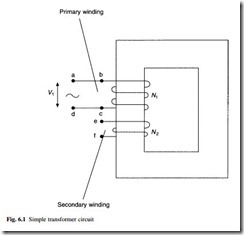
With no load current flowing, the transformer can be represented by two windings on a common core, as shown in Fig. 6.1. It has been explained in Chapter 2 (eqns 2.25 and 2.26) that the input and output voltages and currents in a transformer are related by the number of turns in these two windings, which are usually called the primary and secondary windings. These equations are repeated here for convenience.
Equation 6.3 represents a key relationship between the frequency, the number of turns in a winding and the size of the core. If the winding turns are increased, the core cross- sectional area may be reduced. If the frequency is increased (from 50 to 60 Hz), the size of the core can be reduced.
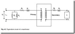
In the no-load case, a small current I0 flows to supply the magnetomotive force which drives the magnetic flux around the transformer core; this current lags the primary voltage by almost 90°. This I0 is limited in magnitude by the effective resistance (Rc) and reactance (Xc) of the magnetizing circuit, as shown in Fig. 6.2. The magnetizing current is typically 2–5 per cent of the full load current and it has a power factor in the range 0.1–0.2.
When the transformer is loaded, there is an internal voltage drop due to the current flowing through each winding. The voltage drops due to the primary and secondary winding resistances (R1 and R2) are in phase with the winding voltage, and the voltage drops due to the primary and secondary winding leakage reactances (X1 and X2) lag the winding voltage by 90°. The leakage reactances represent those parts of the trans- former flux which do not link both the windings; they exist due to the flow of opposing currents in each winding and they are affected strongly by the winding geometry.
The current flow and voltage drops within the windings can be calculated using the equivalent circuit shown in Fig. 6.2. This circuit is valid for frequencies up to 2 kHz.
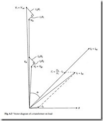
A vectorial representation of the voltages and currents is shown in Fig. 6.3 for the case of a load L with a power factor angle F .
The decrease in output voltage when a transformer is on load is known as regulation.
The output voltage is less than the open-circuit voltage calculated according to eqn 6.1 because of voltage drops within the winding when load current flows through the resistive and reactive components shown in Fig. 6.2. The resistive drops are usually much smaller than the reactive voltage drops, especially in large transformers, so the impedance Z of the transformer is predominantly reactive. Regulation is usually expressed as a percentage value relating the vector addition of the internal voltage drops (shown in Fig. 6.3) to the applied voltage.
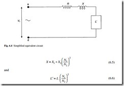
For many applications, the equivalent circuit shown in Fig. 6.2 can be simplified by ignoring R and X, and referring R2 , X2 and L to the primary side as shown in Fig. 6.4, where
Equations 6.4 and 6.5 indicate how resistance and reactance values can be referred from secondary to primary windings (and vice versa) using the square of the turns ratio. Equation 6.6 is used to refer impedances between secondary and primary circuits, allowing circuits to be normalized using the square of the turns ratio, so that simple circuit calculations can be made.
The impedance of the transformer is given by:
Values for R1 and R2 can be established by measuring the resistance of the windings. The value of X is determined by calculation or by derivation from the total impedance Z, which can be measured with one winding of the transformer short circuited. This Z is given by
where V is the voltage necessary to circulate the full-load current I in the windings under short circuit conditions. When V is expressed as a percentage of rated voltage, this gives Z as a percentage value referred to rated power.
When the transformer is energized, but without a load applied, the no-load power loss is due to the magnetic characteristics of the core material used and the flow of eddy currents in the core laminations. The loss due to magnetizing current flowing in the winding is small and can be ignored.
When the transformer is loaded, the no-load loss is combined with a larger component of loss due to the flow of load current through the winding resistance. Additional losses on load are due to eddy currents flowing within the conductors and to circulating currents which flow in metallic structural parts of the transformer. The circulating currents are induced by leakage flux which is generated by the load current flowing in the windings and they are load dependent. These additional losses are known as stray losses.
The efficiency of a transformer is expressed as:
where input, output and losses are all expressed in units of power.
The total losses consist of the no-load loss (or iron loss) which is constant with voltage and the load loss (or copper loss) which is proportional to the square of load current. Total losses are usually less than 2 per cent for distribution transformers, and they may be as low as 0.5 per cent in very large transformers.
When losses are considered in kilowatt values, the lowest loss transformer is found to have no-load loss and loss values approximately equal. However, since many distribution and transmission transformers usually operate at only one-half or one-quarter of full load current, the equal losses criterion is an over simplification.
No-load and load losses are often specified as target values by the user for larger transformers, or they may be evaluated by the capitalization of losses. The capitalization formula is of the type:
Values assigned to capitalization rates for no-load and load loss vary with the load operating regime of the transformer, the discount rate and forward interest rates. Typical capitalization rates for transmission transformers are £ 4000/kW for no-load loss and £ 1000/kW for load loss. Where a purchaser is responsible for the cost of losses the capitalization formulae are respected, but when a purchaser can pass the cost of losses on to a consumer, transformers are purchased at the lowest capital cost.


