Solid-state regulators
Transistorized regulators are capable of exceedingly fine regulation, partially because there are no moving parts. Durability is exceptional. On the other hand any internal malfunction generally means that the unit must be replaced. As a rule, no repairs are possible. Failure can occur because of manufacturing error (this usually shows up in the first few hours of operation and is covered by warranty) high curent draws, and voltage spikes.
The mechanic must be particularly alert when working with transistorized cir- cuits. The cautions that apply to alternator diodes apply with more force to regulators if only because regulators are more expensive. Do not introduce stray voltages, cross connections, reverse battery polarity, or open connections while the engine is running.
The regulator might be integral with the alternator or might be contained in a separate box. In general, no adjustment is possible; however, the Lucas 4TR has a voltage adjustment on its bottom, hidden under a dab of sealant.
Batteries
The battery has three functions: provide energy for the starting motor; stabilize voltages in the charging system; and, for limited periods, provide energy for the accessories in the event of charging-circuit failure. Because it is in a constant state of chemical activity and is affected by temperature changes, aging humidity and cur- rent demands, the battery requires more attention than any other component in the electrical system.
Battery ratings
Starting a diesel engine puts a heavy drain on the battery, especially in cold cli- mates. One should purchase the best quality and the largest capacity practical. The physical size of the battery is coded by its group number. The group has only an indirect bearing on electrical capacity but does ensure that replacements will fit the original brackets. In some instances a larger capacity battery might require going to another group number. Expect to modify the bracket and possibly to replace one or more cables.
The traditional measure of a battery’s ability to do work is its ampere-hour (A-hr) capacity. The battery is discharged at a constant rate for 20 hr. so that the potential of each cell drops to 1.75V. A battery that will deliver 6A over the 20-hr period is rated at 120 A-hr. (6A X 20hr.). You will find this rating stamped on re- placement batteries or in the specifications.
Like all rating systems, the ampere-hour rating is best thought of as a yardstick for comparison between batteries. It has absolute validity only in terms of the orginally test. For example, a 120 A-hr. battery will not deliver 120A for 1 hr., nor will it deliver 1200A for 6 minutes.
Cranking-power tests are more meaningful because they take into account the power loss that lead-acid batteries suffer in cold weather. At room temperature the battery develops its best power; power output falls off dramatically around 0°F. At the same time, the engine becomes progressively more difficult to crank and more reluctant to start. Several cranking-power tests are in use.
Zero cranking power is a hybrid measurement expressed in volts and minutes. The battery is chilled to 0°F; depending on battery size, a 150 or 300 A load is applied. After 5 seconds the voltage is read for the first part of the rating. Discharge continues until the terminal voltage drops to 5V. The time in minutes between full charge and effective exhaustion is the second digit in the rating. The higher these two numbers are for batteries in the same load class, the better.
The cold cranking performance rating is determined by lowering the battery temperature to 0°F (or, in some instances, 20°F) and discharging for 30 seconds at such a rate that the voltage drops below 1.2V per cell. This is the most accepted of all cold weather ratings and has become standard in specification sheets.
Battery tests
As the battery discharges, some of the sulfuric acid in the electrolyte decomposes into water. The strength of the electrolyte in the individual cells is a reliable index of the state of charge. There are several ways to determine acidity, but long ago technicians fixed on the measurement of specific gravity as the simplest and most reliable.
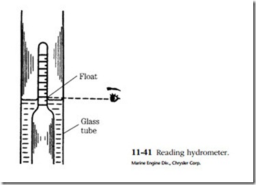
The instrument used is called a hydrometer. It consists of a rubber bulb, a bar- rel, and a float with a graduated tang. The graduations are in terms of specific gravity. Water is assigned a specific gravity of 1. Pure sulfuric acid is 1.83 times heavier than water and thus has a specific gravity of 1.83. The height of the float tang above the liquid level is a function of fluid density, or specific gravity. The battery is said to be fully charged when the specific gravity is between 1.250 and 1.280.
An accurate hydrometer test takes some doing. The battery should be tested prior to starting and after the engine has run on its normal cycle. For example, if the engine is shut down overnight, the test should be made in the morning, before the first start. Water should be added several operating days before the test to ensure good mixing. Otherwise the readings can be deceptively low.
Use a hydrometer reserved for battery testing. Specifically, do not use one that has been used as an antifreeze tester. Trace quantities of ethylene glycol will shorten the battery’s life.
Place the hydrometer tip above the plates. Contact with them can distort the plates enough to short the cell. Draw in a generous supply of electrolyte and hold the hydrometer vertically. You might have to tap the side of the barrel with your finger- nail to jar the float loose. Holding the hydrometer at eye level, take a reading across the fluid level. Do not be misled by the meniscus (concave surface, Fig. 11-41) of the fluid.
American hydrometers are calibrated to be accurate at 80°F. For each 10°F above 80°F, add 4 points (0.004) to the reading; conversely, for each 10°F below the standard, subtract 4 points. The standard temperature for European and Japanese hydrometers is 20°C, or 68°F. For each 10°C increase add 7 points (0.007); subtract a like amount for each 10°C decrease. The more elaborate hydrometers have a built- in thermometer and correction scale.
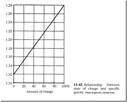
All cells should read within 50 points (0.050) of each other. Greater variation is a sign of abnormality and might be grounds for discarding the battery. The relation- ship between specific gravity and state of charge is shown in Fig. 11-42.
The hydrometer test is important, but by no means definitive. The state of charge is only indirectly related to the actual output of the battery. Chemically the battery might have full potential, but unless this potential passes through the straps and terminals, it is of little use.
Perhaps the single most reliable test is to load the battery with a rheostat or car- bon pile while monitoring the terminal voltage. The battery should be brought up to full charge before the test. The current draw should be adjusted to equal three
times the ampere-hour rating. Thus, a 120 A-hr. battery would be discharged at a rate of 360A. Continue the test for 15 seconds and observe the terminal voltage. At no time should the voltage drop below 9.5V.
In this test, sometimes called the battery capacity test, we used voltage as the telltale. But without a load, terminal voltage is meaningless. The voltage remains almost constant from full charge to exhaustion.
Battery maintenance
The first order of business is to keep the electrolyte level above the plates and well into the reserve space below the filler cap recesses. Use distilled water. Tap water might be harmful, particularly if it has iron in it.
Inspect the case for cracks and acid seepage. Periodically remove the cable clamps and scrape them and the battery terminals. Look closely at the bond between the cables and clamp. The best and most reliable cables have forged clamps, solder-dipped for conductivity. Replace spring clip and other clever designs with standard bolt-up clamps sweated to the cable ends. After scraping and tightening, coat the terminals and clamps with grease to provide some protection from oxidation.
The battery case should be wiped clean with a damp rag. Dirt, spilled battery acid, and water are conductive and promote self-discharge. Accumulated deposits can be cleaned and neutralized with a solution of baking soda, water, and detergent. Do not allow any of the solution to enter the cells, where it would dilute the elec- trolyte. Rinse with clear water and wipe dry.
Charging
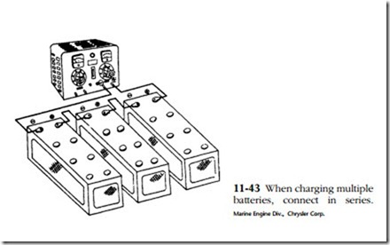
Any type of battery charger can be used—selenium rectifier, tungar rectifier, or, reaching way back, mercury arc rectifier. Current and voltage should be monitored and there should be a provision for control. When charging multiple batteries from a single output, connect the batteries in series as shown in Fig. 11-43.
Batteries give off hydrogen gas, particularly as they approach full charge. When mixed with oxygen, hydrogen is explosive. Observe these safety precautions:
• Remove all filler caps (to prevent pressure rise should the caps be clogged).
• Charge in a well-ventilated place remove from open flames or heat.
• Connect the charger leads before turning the machine on. Switch the machine off before disconnecting the leads.
In no case should the electrolyte temperature be allowed to exceed 115°F. If your charger does not have a thermostatic control, keep track of the temperature with an ordinary thermometer.
Batteries can be charged by any of three methods. Constant-current charging is by far the most popular. The charging current is limited to one-tenth of the ampere- hour rating of the battery. Thus a 120 A-hr. battery would be charged at 12 A. Specific gravity and no-load terminal voltage are checked at 30-minute intervals. The battery might be said to be fully charged when both values peak (specific gravity 1.127–1.129, voltage 15–16.2V) and hold constant for three cranking intervals.
A quick charge, also known as a booster or hotshot, can bring a battery back to life in a few minutes. The procedure is not recommended in any situation short of an emergency, because the high-power boost will raise the electrolyte temperature and might cause the plates to buckle. Disconnect the battery cables to isolate the generator or alternator if such a charge is given to the battery while it is in place.
A constant-voltage charge can be thought of as a compromise between the hot- shot and the leisurely constant-current charge. The idea is to apply a charge by keeping charger voltage 2.2–2.4 V higher than terminal voltage. Initially the rate of charge is quite high; it tapers off as the battery approaches capacity.
Battery hookups
One of the most frequently undertaken field modifications is the use of additional batteries. The additional capacity makes starts easier in extremely cold weather and adds reliability to the system.
To increase capacity add one or more batteries in parallel—negative post connected to negative post, positive post to positive post. The voltage will not be affected, but the capacity will be the sum of all parallel batteries.
Connecting in series—negative to positive, positive to negative—adds voltage without changing capacity. Two 6V batteries can be connected in series to make a physically large 12V battery.
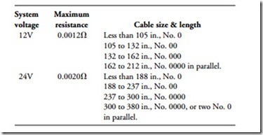
Cable size is critical because the length and cross-sectional area determine resistance. Engineers at International Harvester have developed the following recommendations, which can be applied to most small, high-speed diesel engines:
• Use cables with integral terminal lugs.
• Use only rosin or other noncorrosive-flux solder.
• Terminal lugs must be stacked squarely on the terminals. Haphazard stack- ing of lugs should be avoided.
• Where the frame is used as a ground return, it must be measured and this distance added to the cable length to determine the total length of the sys- tem. Each point of connection with the frame must be scraped clean and tinned with solder. There should be no point of resistance in the frame such as a riveted joint. Such joints should be bridged with a heavy copper strap.
• Pay particular attention to engine-frame grounds. If the engine is mounted in rubber it is, of course, electrically isolated from the frame.
• Check the resistance of the total circuit by the voltage drop method or by means of Ohm’s law (R = E/I).
• Use this table as an approximate guide to cable size for standard-duty cranking motors.
• Suggested battery capacity varies with system voltage (the higher the volt- age, the less capacity needed for any given application), engine displacement, compression ratio, ambient air temperature, and degree of exposure. Generalizations are difficult to make, but typically a 300 CID engine with a 12V standard-duty starter requires a 700A battery for winter operation. This figure is based on SAE J-5371 specifications and refers to the 30-second out- put of a chilled battery. At 0°F capacity should be increased to 900A. The International Harvester 414 CID engine requires 1150, or 1400A at 0°F. Battery capacity needs roughly parallel engine displacement figures, with some flattening of the curve for the larger and easier-to-start units. In extremely cold weather—below -10°F—capacity should be increased by 50% or the batteries heated.
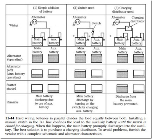
• RV and boat owners often install a second battery to support accessory loads. Arranging matters so that there is always power available for starting requires special hardware; otherwise, the state of charge of either battery is the average of the two. Figure 11-44 illustrates this proposition.
