Effects of Harmonic on Power System Equipment and Loads
The HD of concern here is the nonfundamental periodic voltage resulting from the steady state operation of nonlinear elements connected to the power distribution system. This periodic voltage often, but not always, consists of harmonics of the power system fundamental frequency. The effect of voltage distortion may be divided into three general categories:
(1) insulation stress due to voltage effects, (2) thermal stress due to current flow, and (3) load disruption. Load disruption is defined as objectionable abnormal operation or failure caused by voltage distortion. While this definition is general enough to include such items as torques generated in electromechanical devices, load disruptions appear to b e limited to the various types of solid-state loads. In this section we offer a discussion on general concepts involved in evaluating the effects of harmonics on power apparatus, to provide quantitative analysis of the effects and to identify potential problems.
12.5.1 Basic Concepts on Effects of Harmonics
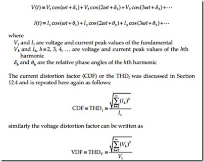
A distorted periodic voltage or current waveform can be expanded into a Fourier series to give the harmonic terms by the following equations:
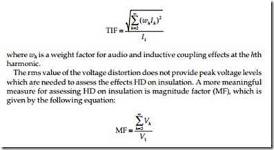
Harmonics also generate telephone interference through inductive coupling. The telephone interference is defined as telephone influence factor (TIF) which is expressed as follows:
The distortion factors, current, voltage (rms and peak), and telephone influence are utilized to describe the quantitative effect of the harmonics on electric loads and other apparatus. For example, the CFD is useful in quantifying the copper losses in a constant resistance load, the TIF to quantify telephone interference, MF in assessing dielectric stress, etc. In general, the diversity of the effects of harmonics makes it extremely unlikely that any one measure of voltage distortion will adequately describe all effects. A better approach is to identify the sensitivities of apparatus performance to distortion factors, and thereby, identify the relative usefulness of these parameters. The effects of harmonics on thermal stress, insulation stress, and load disruption are discussed as follows.
Thermal Stress
In general, the presence of harmonic current increases the losses and thus the thermal stress of the equipment. The losses are copper losses, iron losses, and dielectric losses. In a given power equipment, one or more of above losses may determine the thermal stress of the device. These losses can be computed as follows:
Copper losses: The copper losses (PC) can be computed with the following general formula
where Ih is the peak value of the hth harmonic current, Rh is the resistance of the apparatus at the hth harmonic.
In cases where resistance of the apparatus is constant (independent of frequency), the copper losses can be written in terms of the CDF as follows;
As shown in the equation above, the CFD determines the increase of copper losses due to the presence of harmonics. In general, however, the resistance of power apparatus increases with frequency because of the skin effect. The impact of skin effect on harmonic losses becomes more important in large diameter conductors and deep bar induction motors.
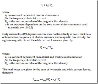
Iron losses: Iron losses are made up of (1) hysteresis loss and (2) eddy current loss. These losses are given by the following formulas:
Hysteresis loss (Ph) is a function of magnetic material used and frequency of the current. For a given magnetic core, the hysteresis loss is equal to
The total iron loss is a nonlinear function of frequency and maximum magnetic flux density. For a given voltage harmonic, the frequency is known and the maximum magnetic flux density is proportional to the harmonic current. The constant of proportionality depends on coil and magnetic core design. The equation for iron loss is valid for a sinusoidal excitation of the power apparatus of frequency f. In case the excitation source is polluted with harmonics, one can cautiously use the equation for iron loss to compute the iron loss for each harmonic and add the contributions. This procedure (superposition) is correct only for linear apparatus. Because of magnetic saturation and magnetic hysteresis, magnetic circuits are not exactly linear systems. However, for normally encountered operating con- ditions and level of harmonics, superposition can be used as a reasonable approximation.
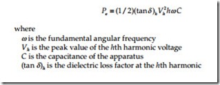
Dielectric losses: The dielectric losses are applicable to cables and capacitors and at a given harmonic, h, are given by the following equation
Insulation Stress
Insulation stress primarily depends on instantaneous voltage magnitude and voltage rate of increase secondarily. The presence of voltage harmonics can result in an increase of the crest value of the voltage and thus increased insulation stress. This increase is not of concern for most power system apparatus because they are insulated for much higher voltage levels than those usually encountered from harmonics. Capacitor banks, however, are very sensitive to overvoltages and must be protected against overvoltages resulting from harmonics. A special discussion is provided later in this section. The voltage rate of increase is important in switchgear and it is discussed in this section also. An area of possible concern is the effect of voltage distortion on surge protective devices, including the sparkover and recovery of gapped surge arresters.
Load Disruption
Load disruption is defined as objectionable abnormal operation or failure caused by voltage distortion. Many electronic equipment are susceptible to load disruption because their normal operation depends on the existence of a sinusoidal voltage source. The effects of the harmonics on electronic equip- ment are discussed later in this section. Load disruption also includes decreases of useful magnetic electromagnetic torque in electric machinery because of the presence of harmonics. Specifically, current harmonics
circulating in the armature of electric machinery may generate pulsating or constant electromagnetic torques. Pulsating torques result in equipment wear and shortening of equipment life. Constant torques, in most cases, reduce the useful electromagnetic torque and, result in reduced efficiency.
Harmonic Effects on Power System Equipment
Transformers
The effects of harmonics on transformers are
• Increased copper losses
• Increased iron losses
• Possibly resonance between transformers
• windings and line capacitance
• Insulation stress
• Neutral overheating due to triplen harmonics
The copper losses and iron losses in the presence of harmonics can be com- puted with the general equations presented in Section 12.5.1.1. The application of general equations given in Section 12.5.1.1 assumes that the transformer is a linear device which it is not. However, for normal, operating conditions and normal levels of harmonics, this is a reasonable approximation. Similarly, an approximate expression for total hysteresis losses can be determined by using the equations given in Section 12.5.1.1. However, the increase of hysteresis losses due to harmonics is only a fraction of the eddy current losses.
Voltage harmonics result in higher transformer voltage, therefore higher insulation stress. This is not a problem since most transformers are insulated for much higher voltage levels than the overvoltages due to usual levels of harmonics. There is a certain degree of interaction between volt- age and current harmonics for transformers designed to operate near the saturation point (knee of the saturation curve). It is possible a small level of voltage harmonic to generate a high level of current harmonics. This phenomenon depends on specific harmonic and phase relationship to the fundamental. To address the overheating of transformers due to harmonics, the ANSI/IEEE published a standard C57.110-1998, “Recommended practice for establishing transformer capability when supplying nonsinusoidal load currents,” which was reaffirmed in 2004. This standard establishes methods for determining derating factors for transformer capability to carry nonsinusoidal load currents.
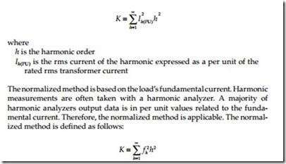
In 1990, Underwriters Laboratory (UL) established the method for testing transformers that serve nonlinear loads. The UL test addresses coil heating due to nonlinear loads and overheating of the neutral conductor by assigning a “K“ factor to the transformer. The K-factor is meant to apply to trans- formers serving general nonlinear loads. UL has devised the K-factor method for labeling and rating the ability of dry-type transformers to withstand the effects of harmonics. The K-factor rating indicates the transformer’s ability to tolerate the additional heating caused by harmonics. The K-factor is based on the methodology similar to that discussed in the ANSI/IEEE C57.110 standard. The K-factor can be calculated as the sum of the product of each harmonic current squared and that harmonic number squared for all harmonics from the fundamental to the highest harmonic of consequence. When K-factor is multiplied by the stray losses of the transformer, the result represents the total stray losses in the transformer caused by harmonic currents. To obtain the total load losses, the total stray losses are then added to the load losses. It should be obvious that the K-factor for linear loads (absence of harmonics) is 1. Also, the K-factor does not mean that the transformer can eliminate harmonics. Harmonics increase heating losses in all transformers, and some of these losses are deep within the core and windings and some are closer to the surface. Oil-filled trans- formers react differently to the increased heat and are better able to cool whereas dry-type transformers are more susceptible to the harmonic cur- rent effects and are so labeled. The UL test addresses coil heating due to nonlinear loads and overheating of the neutral conductor.
There are two methods for calculating K-factor. They are UL method and normalized method. The UL method, based on the transformer’s rated rms current, is generally used when rms current is measured. The UL method is defined as follows:
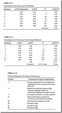
where fh is the fundamental current in per unit (the first harmonic = 100%) An example of the two methods for the same harmonic spectrum of data is given in Tables 12.2 and 12.3.
The K-factor rating of dry-type transformers is available from 1 through 50. However, for majority of application rating of 20 or less should suffice. Table 12.4 lists the available K-factor rated transformers.
The basic sources of data for computing K-factor are from measurements or estimates. Exercise care in measuring loads so the data is accurate and simulates the transformer at full load. When estimating loads, the computed K-factor is usually overly conservative (large) as it does not take into account potential harmonic phase cancellations. To address this, UL has specified that the rms current of any single harmonic greater than the 10th be considered as no greater than 1/h of the fundamental rms current. This attempts to compensate for otherwise conservative computed impacts of higher frequencies. Equipment manufacturers can be a source of data for nonlinear loads. As K-factor increases, the transformer becomes larger and its impedance decreases markedly. Lower source impedance can result in higher distortion, which can aggravate a problem instead of solving it.
Another problem that occurs with transformers is the overheating of the neutral in a three-phase four-wire power distribution system. When single- phase nonlinear loads are connected to the secondary of a wye–delta trans- former, such as is found in many industrial and commercial applications, the triplen harmonics (third, ninth, and so on) algebraically add up in the neutral of the secondary of the transformer. These currents are often in excess of the phase currents and therefore cause overheating of the neutral conductor, components, bus bars, etc. Also these currents are reflected back into the delta primary windings where they circulate and cause the trans- former to overheat or fail.
Rotating Machines
The effects of harmonics in rotating machinery are increased heating due to copper and iron losses, changes in electromagnetic torque which affect, machine efficiency and machine torsional oscillations. The level and importance of these effects depend on electric machine design and harmonic source type. Electric machines can be classified as synchronous machines (three-phase), three-phase induction machines and single-phase induction motors. On the other hand, the source of harmonics for three-phase systems may be a balanced three-phase source or may be a single-phase source injecting harmonics in one phase only. The latter case can be analyzed with the use of symmetrical components which is applicable to each one harmonic. Thus for three-phase electric machinery only the effects of balanced three- phase harmonic excitation need to be examined. The effects of single-phase harmonic excitation can be deduced from the former. A good understanding of the effects of harmonics on rotating machinery requires a good understanding of the electromagnetic fields inside the machines due to harmonic currents. Because of the complex construction of rotating machinery, the frequency of the magnetic flux may not coincide with the frequency of the armature currents. In addition, at a given harmonic, the frequency of the magnetic flux in the rotor is different of the frequency in the stator. The below listed observations can be used for analyzing the effects of harmonics on rotating machines.
1. The zero sequence harmonics (h = 3, 6, 9, 12, …) do not produce a net magnetic flux density. Thus the only effect they produce is ohmic losses.
2. The positive sequence harmonics (h = 1, 4, 7, 10, 13, …) produce a rotating magnetic flux which rotates with speed hw in the positive direction and magnitude proportional to the harmonic current. The relative speed of the rotating magnetic field with respect to the rotor is (h − 1)w [or (h − 1 + S)w for induction machines, S = slip]. Because of induction motor action, an electromagnetic torque will be devel- oped in the direction of rotation. The frequency of the alternating magnetic flux is 60 h in the stator and 60(h − 1) in the rotor. These frequencies determine the iron losses which occur partly in the stator and partly in the rotor.
3. The negative sequence harmonics (h = 2, 5, 8, 11, …) produce a rotat- ing magnetic flux which rotates with speed −hw (opposite to the direction of rotation) and magnitude proportional to the harmonic current. The relative speed of the rotating magnetic field with respect to the rotor is −(h + 1)w [(or −(h + 1 − S)w for an induction machine, S = slip)]. Because of induction motor action, an electromagnetic torque will be developed in a direction opposite to that of rotation. The frequency of the alternating magnetic flux is 60 h in the stator and 60(h + 1) in the rotor.
The performance of an induction motor, operating from a supply voltage rich in harmonics, deteriorates because the presence of negative sequence harmonics generates opposing torque and the presence of any harmonic increases copper and iron losses. These effects result in a net derating of the motor.
Another effect results from the interaction of the magnetic field generated by a harmonic and the fundamental magnetic field. Consider, for example, the seventh harmonic in a synchronous, machine. The seventh harmonic magnetic field rotates, relatively to the rotor field, with a speed (h − 1)w . The interaction of the two fields will produce a pulsating torque of fre- quency 60(h − 1) = 360 Hz. In the same way, the fifth harmonic will gener- ate a pulsating torque of frequency 60(h + 1) = 360 Hz. Thus pairs of harmonics generate pulsating torques of frequency 180, 360, 540 Hz, etc. In a typical system, the 360 Hz pulsating torque is substantial and results in oscillations of the machine shaft. It is possible that the natural fre- quency of the machine is in the vicinity of this frequency. In this case, the fifth and seventh harmonics may excite a super synchronous resonance condition which involves torsional oscillations of the rotor elements. Supersynchronous resonance occurs when the frequency of a mode of mechanical vibration exists close to the frequency of electrical stimulus. In this case, high resonant mechanical oscillations may be developed which could result in fatigue of the shafts.
The pulsating torques, due to the presence of harmonics, also result in higher noise emission as compared with pure sinusoidal excitation.
The ANSI standards C50.13-2005, American National Standard Requirements for Cylindrical-Rotor Synchronous Generators, defines a limit on the negative sequence current (60 Hz) for generators operating continuously at rated kVA and maximum current not exceeding 105% (of rated) in any phase.
Capacitor Banks
Capacitor impedance decreases with frequency. For this reason, capacitor banks act as sinks of harmonics. In a system with distributed harmonic sources, the harmonics will converge to the capacitor bank. As a result most harmonic problems show up first at shunt capacitor banks. Severe harmonic problems at capacitor banks manifest themselves with (1) fuses blowing and (2) capacitor canister (can) failure. The presence of harmon- ics at capacitor banks can cause:
• Increased dielectric losses and thus heating
• Resonance conditions resulting in magnification of harmonics
• Overvoltages
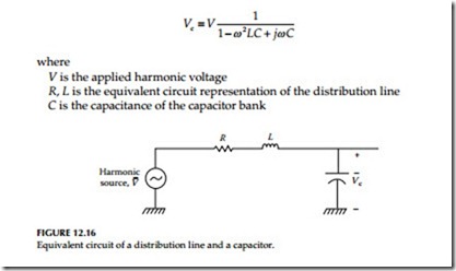
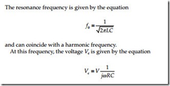
Distribution line capacitor banks: Distribution capacitor banks can form a resonant circuit with the inductance of distribution lines at a frequency near the harmonics of interest. In this case, the harmonics may be amplified at the capacitor location. Consider, for example, a portion of an overhead distribu- tion circuit represented for simplicity with an R, L circuit, a capacitor bank, and a source of harmonics as in Figure 12.16.
The harmonic voltage, Vc, at the capacitor bank is given by the equation:
Today computer programs are available to predict these resonance conditions and the harmonic frequency can be predicted with which the capacitor will resonate. Therefore, this effect can be mitigated by installing a correct filter to shunt the harmonic currents thereby avoiding the resonance condition.
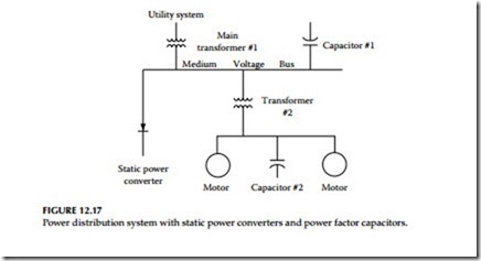
PF correction capacitor banks: Every power capacitor installation is in parallel with the inductance of the power system, and this combination is in resonance at some frequency. If this frequency is at one of the static power converters characteristic harmonics, the current of that harmonic can excite the resonant circuit and cause an oscillating current to be exchanged between the two energy storage elements. These high harmonic currents can produce high harmonic voltages which in turn can force harmonic currents to flow in adjacent circuits. This diversity of conditions makes it hard to determine if all parameters are going to be present to cause problems. This happens enough times to make system designers nervous when the combination of static power converters and power factor capacitors occurs on the same power system (see Figure 12.17).
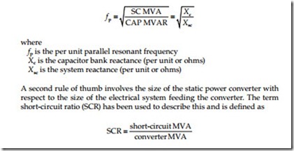
Criteria for trouble: There are some quick rules of thumb that might be used to determine if there might be a problem. The first is the resonant value of the combination of the system impedance and the capacitor bank size:
If the converter is small compared to the system capacity, the per-unit harmonic currents will be small and the system impedance will be low, so any harmonic voltage will be insignificant. If the SCR is above 20 and the fp is above 8.5, the probability of problems is low. If the SCR is below 20, and if the parallel resonance fp is near one of the converter characteristic harmonics, there is a high probability of producing excessive harmonic voltage and high harmonic currents. The increased use of static power converters and power factor capacitors can set up system conditions to cause problems. However, with the judicial design of filters using the power factor capacitors to control the harmonic currents from the static power converters, both pieces of equipment can be used to take full advantage of all the economics that both of them offer.
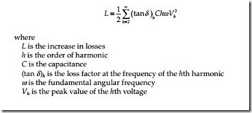
Another effect of the harmonic components on the capacitor bank is to cause additional heating because of increased dielectric losses. The increased losses due to harmonics may be calculated with
The overvoltage appearing at a capacitor bank due to the presence of harmonics depends on the phase relationship of harmonic and fundamental voltages. It is possible that the instantaneous overvoltage is greater than the rms overvoltage. As the corona inception and extinguishing voltage levels are a function of peak voltage, and not rms voltage, the life of the capacitor could be affected due to corona discharges. Capacitors, unlike most other power appara- tus, have strict limits on current, kVAR, and voltage. The IEEE 18-2002, “Shunt power capacitors,” specifies the limit on harmonics that the shunt capacitors can be subjected to under normal operation. The standard states that the capacitor may be continuously operated in the presence of harmonics provided (1) the total reactive power is not greater than 135% of its rated value, (2) the current due to the fundamental and harmonic frequency components does not exceed 180% of rated rms value, and (3) the rms value of the applied voltage is not more than 110% of rated terminal voltage and the crest value (1.2 × (square root of two) ) of the applied voltage does not exceed 120% of rated peak voltage.
Switchgear
Harmonic components in the current waveform can affect the interruption capability of the switchgear. This takes place with two distinct mechanisms:
(1) the presence of harmonics affects the rate of rise of the transient recovery voltage and the maximum value of the transient voltage and (2) harmonics affect the operation of the blowout coil in the stored-energy breakers. These effects will be discussed next.
The presence of current harmonics may result in high di/dt values at current zero. In this case, the rate of rise of the transient recovery voltage across the breaker will be higher than normal creating the possibility of dielectric failure and restrike. Also, the presence of harmonic currents affects the time that current crosses zero. This time affects the crest value of the transient recovery voltage. For example, if this time coincides with the maxi- mum of the source voltage (fundamental), the crest value of the transient recovery voltage can reach 2.82 E where E is the rms value of the rated volt- age. This value may cause breaker restrike. Circuit breakers have failed to interrupt currents due to the inability of the blowout coils to operate adequately in the presence of severe harmonics. As the blowout coil assists in the arc’s movement into the arc chute where the interruption takes place, its inefficient operation prolongs arcing and eventually results in breaker failure. Similar problems can exist in other current interrupting devices such as load break switches, circuit switchers, etc. Vacuum breakers are less sensitive to harmonic currents. There are no definite standards set forth by the industry on the level of harmonic currents that switching devices are required to interrupt. All the interrupting tests are performed at the rated supply frequency. The effect of harmonics on transient recovery voltage is by far the most difficult because it depends on specific system configuration.
One of the principal problems due to harmonics is the one that occurs within the switchgear neutral of three-phase four-wire systems when harmonics are present. The problem associated with neutrals is the result of the addition of triplen harmonic currents (i.e., multiple of the third harmonic) to the funda- mental current in the neutral. The result often is that the neutral, which would normally carry very little current in a balanced three-phase system, now carries currents in excess of the phase currents for the system. Since neutral conductors, lugs, bus bars, etc, often are sized smaller than phase conductors and current components, the result is that the neutral system components are overloaded and often overheat, fail, or even burn down.
Protective Relays
Relays that depend on voltage/current crest or voltage zeroes for their operation are obviously affected by HD. System harmonics affect relay operation in a very complex manner. The induction disk and electromechanical relays are affected in the following way. The presence of harmonic currents results in additional torque components altering the time delay characteristics of the relays. Ground relays cannot distinguish between zero sequence current and third harmonic current. Thus, the presence of excessive third harmonic cur- rent can cause ground relays to trip. A recent Canadian study documents the effects of harmonics on relay operation as follows:
1. Relays exhibited a tendency to operate slower and/or with higher pickup values rather than to operate faster and/or with lower pickup values.
2. Static underfrequency relays were susceptible to substantial changes in operating characteristics.
3. In most cases, the changes in operating characteristics were relatively small over the moderate range of distortion expected during normal operation.
4. Depending on the manufacturer, the overvoltage and overcurrent relays exhibited various changes in operating characteristics.
5. Depending on harmonic content, operating torques of relays can be reversed.
6. Operating times can vary widely as a function of frequency mix in the metered quantity.
7. Balanced beam impedance relays can exhibit both overreach and underreach.
8. Harmonics can impair the high speed operation of differential relays. Several tests indicated that the relays could exhibit complete restraint.
In general, the harmonic levels required to cause misoperation of relays are greater than levels which would be considered maximum acceptable limits for other equipment. Harmonic levels of 10%–20% are generally required to cause problems with relay operation, except in unusual circumstances.
Metering Devices
Metering and instrumentation are affected by the presence of voltage and current harmonics. Induction disk devices, such as watt-hour meters and overcurrent relays, are designed and calibrated only for the fundamental current and voltage. The presence of harmonic currents and voltages generates additional electromagnetic torque on the disk which can cause erroneous operation. A Canadian study indicates that a 20% fifth harmonic content can produce 10%–15% error in a two element three-phase watt transducer. Other studies have shown that the error due to harmonics may be positive, negative, or smaller with third harmonics. This, of course, is dependent on the type of meter under consideration. Solid-state meters can measure power based on waveshape. In general, the distortion must be severe (>20%) before significant errors are detected.
Electronic Equipment
In many cases, electronic equipment are significant sources of harmonics. On the other hand, the operation of electronic equipment is often dependent on accurate determination of voltage zero crossings or other aspects of the voltage waveshape. For example, HD can result in a shifting of the zero crossing of the voltage waveform. This may be critical for many types of electronic circuit controls, and misoperation, such as commutation failures, can result from the shifts of the zero crossing. A large class of loads utilize energy in some form other than at the incoming line frequency, and require rectification or frequency conversion. External distortion may affect the performance of either the power converter or the converter load. The severity of these effects are influenced by the equipment design. Analysis of these effects is complicated by the fact that the converter itself is a complex nonlinear apparatus producing its own harmonics. Inverters used for DC to AC conversion or vice versa, generate a voltage notch during commutation. Voltage notching effects are of sufficient concern that notch limits on distorting apparatus have been included in some standards and guidelines. Voltage and current distortion may lead to disruption of the operation of electronic equipment. These disruptions may be divided into two categories: disruption of the converter operation and disruption of the converter load operation. The diversity of converter designs and the wide range of loads fed by these converters makes any general analysis difficult. It can be noted, however, that these disruptions are very much a function of converter design, and that electrical isolation of the sensitive load from loads producing distortion reduces the likeli- hood of disruption. Empirical data and operating experience with steady state voltage and current distortion in industrial plants has led to specific design recommendations summarized in the IEEE standard 519-1992, “IEEE guide for harmonic control and reactive compensation of static power converters.”
Lighting Devices
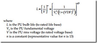
Incandescent lamps: The incandescent lamp is one of the devices of this load group which is most sensitive to increased heating effects. A relative equation for bulb life is given by the equation:
It can be noted that large distortion factors will significantly shorten the bulb life, and that changes in the fundamental voltage are relatively more significant than changes in the distortion factor.
Arc lamps: The various types of arc lamps exhibit nonlinear resistance characteristics where the resistance declines as the current increases. The lamps have a safe operating region, and a ballast is required to place the lamp operating point in the safe region for all line voltage conditions throughout the range of various lamp characteristics. During normal lamp operation, the ballast functions as a current-limiting element. With inductive ballasts, the influence of voltage distortion would be roughly described by the distortion factor. It would appear that modest distortion factors would not cause a large shift in the lamp-operating point. Capacitive ballasts must be viewed with some concern, however, as the ballast reactance would drop as the frequency of the harmonic rises. Because the bulb itself is a highly nonlinear device, it is not at all clear what effect voltage distortion would have on lamps with capacitive ballasts.
