Conducting a Thermographic Survey
The NETA (2005 NETA Maintenance Testing Specifications, Section 9) and NFPA 70B (Section 20.17) contain guidance for conducting thermographic (IR) sur- veys and inspection. It is a necessary requirement that the person performing the thermographic inspection be thoroughly trained and experienced in the apparatus and systems being evaluated, as well as knowledgeable of thermo- graphic principles and methodology.
The following summary of the NETA and NFPA guidance on thermo- graphic surveys and inspection is offered for the reader.
Visual and mechanical inspection: Inspect distribution systems with imaging equipment capable of detecting a minimum temperature difference of 1°C at 30°C. Equipment shall be capable of detecting emitted radiation and convert detected radiation to visual signals. Perform thermographic surveys under maximum loading conditions. Remove all necessary covers prior to perform- ing IR inspection. Use appropriate caution, safety devices, and personal protective equipment when conducting the thermographic surveys.
Report: Provide a report of the thermographic survey and result including the following: description of equipment to be tested; discrepancies found; temperature difference found between the area of concern and the reference area and ambient temperature; provide probable cause of temperature
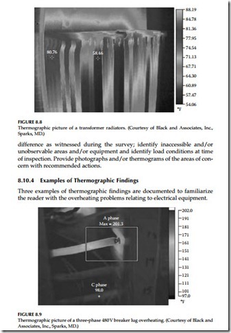
1. The first example is shown in Figure 8.8 which shows transformer radiators being blocked. As can be seen in the survey photograph, the radiators showing darker color are not carrying any oil, i.e., these radiators are blocked. The temperature of radiators on the left-hand side of transformer is measured to be 80.76°F compared to the tem- perature of 58.46°F for the radiators in blue color. If this condition is not corrected, then over time more radiators become blocked and the transformer will overheat.
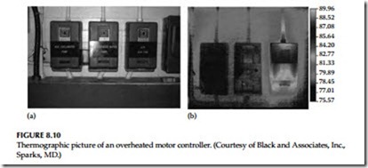
2. The second example shows an overheated three-phase 480 V breaker in Figure 8.9. In this picture, phase A conductor and lug are overheated and show a temperature of 201.3°F compared to 98°F for the other two phases. Apparently the phase A lug and conductor are overheated which could be due to loose connections or high resistance built up at the lug. As discussed earlier just comparing the temperature of the three phases will be a good indication of the actual conditions. However, the Delta-T temperature, or standard-based temperature rating system could be used to provide more detail analysis of the problem.
3. The third example of three motor controllers is shown in Figure 8.10a and b. In Figure 8.10a, three motor controllers are shown mounted side by side and were surveyed with IR camera without removing the covers. In Figure 8.10a, the left hand side controller supplies chilled water pump, the middle controller supplies condensate pump and the right hand side controller supplies auxiliary fan. It is appar- ent from the thermographic picture, as shown in Figure 8.10b, the auxiliary fan controller has excessive heat compared to the other two controllers. Note that the excessive heat is not visible to the naked eye in the picture shown in Figure 8.10a, but is very apparent in the thermographic picture shown in Figure 8.10b. It is obvious that the auxiliary fan controller needs further investigation to determine the cause of excessive heating.

