Power-Generation Systems
Introduction
Any ac power system begins with a generating source. Electric generators are devices that convert energy from a mechanical form into an electrical form. This process, known as electromechanical energy conversion, involves magnetic fields that act as an intermediate medium. The input to the generating machine can be derived from a number of energy sources. For example, in the generation of large-scale electric power, coal can produce steam that drives the shaft of the machine. Typically, for such a thermal process, only about 1/3 of the raw energy (i.e., from coal) is converted into mechanical energy. The final step of the energy conversion is quite efficient, with efficiency close to 100%.
Fundamental Concepts
A simplified diagram of a three-phase generator is shown in Figure 2.1. Note that poles A ‘, B ‘, and C ‘ repre- sent the start of each of the phase windings, whereas poles A, B, and C represent the ends of each of the windings. As with transformers, the windings of the generator can be connected in either of two ways:
• Wye configuration. A circuit arrangement in which the schematic diagram of the windings forms a Y.
• Delta configuration. A circuit arrangement in which the schematic diagram of the windings forms a delta.
Figure 2.2 illustrates the connection arrangements.
The generator shown in Figure 2.1 is a rotating-field type of device. A magnetic field is developed by an external dc voltage. Through electromagnetic induction, a current is induced into each of the stationary (stator) coils of the generator. Because each of the phase windings is separated by 120°, the output voltage of the generator also is offset for each phase by 120° (Figure 2.3). Three-phase power is used almost exclusively for power distribution because it is an efficient method of transporting electrical energy.
Operating Principles
The operation of a generator is based on Faraday’s law of electromagnetic induction [1]: If a coil (or wind- ing) is linked to a varying magnetic field, then an electromotive force (emf or voltage) is induced across the coil. Thus, generators have two essential parts: one that creates a magnetic field, and the other where the emf energies are induced. The magnetic field is typically generated by electromagnets; thus, the field intensity can be adjusted for control purposes. These windings are referred to as field windings or field circuits. The coils where the emf energies are induced are called armature windings or armature circuits. One of these two components is stationary (the stator), and the other is a rotational part (the rotor) driven by an external torque. Conceptually, it is immaterial which of the two components is intended to rotate because, in either case, the armature circuits always experience a varying magnetic field. However, practical considerations lead to the common design that for ac generators, the field windings are mounted on the rotor and the armature windings on the stator.
Today, most electric power is produced by synchronous generators that rotate at a constant speed (the synchronous speed). This speed is dictated by the operating frequency of the system and the machine
structure. AC generators are also used that do not necessarily rotate at a fixed speed, such as those found in windmills (induction generators); these generators, however, account for only a small percentage of the power generated today.
For a better understanding of the principles of operation, see Figure 2.4, which shows a cross section of a basic ac machine. The rotor consists of a winding wrapped around a steel body. A dc current is made to flow in the rotor winding (or field winding), and this results in a magnetic field (rotor field). When the rotor is made to rotate at a constant speed, the three stationary windings aa‘, bb‘, and cc‘ experience a periodically varying magnetic field. Thus, an emf is induced across these windings in accor- dance with Faraday’s law. These forces are ac and periodic; each period corresponds to one revolution of the rotor. Thus, for 60 Hz electricity, the rotor must spin at 3600 rev- olutions per minute (rpm); this is the synchronous speed of the machine. Because the windings aa‘, bb‘, and cc‘ are displaced equally in space from each other (by 120°), their emf waveforms are displaced in time by one third of a period. In other words, the machine is capable of generat- ing three-phase electricity.
When the stator windings are connected to an exter- nal (electrical) system to form a closed circuit, the steady-state currents in the windings are also periodic. This revolving field arises from the space displacements of the windings and the phase differences of their currents. The combined magnetic field has two poles and rotates at the same speed and direction as the rotor. It is important to observe that the armature circuits are in fact exposed to two rotating fields, one of which (the armature field) is
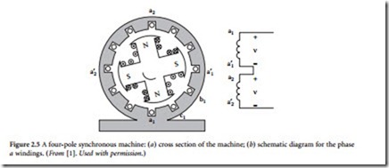
tional view of a four-pole machine is illustrated in Figure 2.5. For the specified direction of the (dc) cur- rent in the rotor windings, the rotor field has two pairs of north and south poles, arranged as shown. The emf induced in a stator winding completes one period for every pair of north and south poles sweeping by; thus, each revolution of the rotor corresponds to two periods of the stator emf. If the machine is to operate at 60 Hz, then the rotor needs to rotate at 1800 rpm. In general, a p-pole machine operating at 60 Hz has a rotor speed of 3600/(p/2) rpm. That is, the lower the number of poles, the higher the rotor speed must be. In practice, the number of poles is dictated by the mechanical system (the prime mover) that drives the rotor. Steam turbines operate best at a high speed; thus, two- or four-pole machines are suit- able. Machines driven by hydro turbines usually have more poles and operate at lower speeds.
The stator windings are typically arranged so that the resulting armature field has the same number of poles as the rotor field. In practice, there are many possible ways to arrange these windings. The essential idea, however, can be understood by studying the arrangement shown in Figure 2.5. Each phase consists of a pair of windings and thus occupies four slots on the stator structure. For example, those for phase a are labeled a1a1‘ and a2a2‘. Geometry suggests that, at any time instant, equal electromotive forces are induced across the windings of the same phase. If the individual windings are connected in series, as shown in Figure 2.5, their energies add up to form the phase voltage.
In addition to the basic components of a synchronous generator (the rotor, stator, and their windings), auxiliary devices are used to help maintain the machine’s operation within acceptable limits. These devices include the following:
• Governor. The function of the governor is to control the mechanical power input to the generator. The control is via a feedback loop where the speed of the rotor is constantly monitored. For instance, if this speed falls behind the synchronous speed, the input is insufficient and has to be increased. This is accomplished by opening a valve to increase the amount of steam for turbogenerators or the flow of water through the penstock for hydrogenerators. Governors are mechanical systems and, therefore, usually have some significant time lags (many seconds) compared to other electromagnetic parameters associated with the machine.
• Damper windings (armortisseur windings). These windings are special conducting bars buried in notches on the rotor surface (the rotor resembles a squirrel-cage-rotor induction machine). The damper windings provide an additional stabilizing force for the machine during certain periods of operation. As long as the machine is in a steady state, the stator field rotates at the same speed as the rotor, and no currents are induced in the damper windings. However, when the speeds of the stator field and the rotor become different (because of a load disturbance), currents are induced in the damper windings in such a way as to keep the two speeds from separating.
• Excitation control system. Modern excitation systems are fast and efficient. An excitation control system is a feedback loop
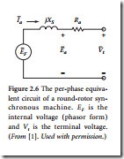
designed to maintain the voltage at the machine terminals at a set level. Figure 2.6 illustrates the mechanisms at work. Assume that a disturbance occurs in the system, and as a result, the machine terminal voltage Vt drops. The excitation system boosts
guarantee stable behavior because the effects of the interconnection and Vt is the terminal voltage.
system and other elements in the network are not taken into account.
An analysis of the operation of centralized control systems is beyond the scope of this book; however, it is instructive to examine some of (From [1]. Used with permission.)
the principles of decentralized control systems. Many of these principles apply in a modified form to centralized control techniques.
Control Techniques
Reliable electric power service implies that the loads are fed at a constant voltage and frequency at all times [1]. A stable power system is one in which the synchronous machines, if perturbed, will return to their original state if there is no net change in power, or stabilize at a new state without loss of synchronization. The machine rotor angle is used to quantify stability; that is, if the difference in the angle between machines increases or oscillates for an extended period of time, the system is considered unstable. The swing equation, given by
governs the motion of the machine rotor. J is moment of inertia, δm is mechanical torque angle with respect to a rotating reference, ωm is shaft angular velocity, and Ta is the accelerating torque. Two factors that act as criteria for the stability of a generating unit are the angular swing of the machine during and following fault conditions, and the time it takes to clear the transient swing.
The mechanical torque of the prime mover — team or hydraulic — for a large generator depends on rotor speed. In an unregulated machine, the torque speed characteristic is linear over the rated range of speeds. The prime mover speed of a machine will drop in response to an increased load, and the valve position must be opened to increase the speed of the machine. In a regulated machine (governor con- trolled), the speed control mechanism controls the throttle valves to the steam turbine or the gate posi- tion for a water turbine.
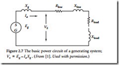
Automatic voltage regulation can be used to adjust the field winding current, thus changing Eg as the load on the machine is varied (Figure 2.7). If the power output of a generator is to be increased while an automatic voltage regulator holds the bus voltage at a constant value, then the field winding current must be increased. The maximum voltage output of a machine is limited
by the maximum voltage of the excitor supplying the field winding. Figure 2.8 illustrates control of a power-generating unit.
The performance of a transmission system can be improved by reactive compensation of a series or parallel type. Series compensation consists of banks of capacitors placed in series with each phase conductor of the line and is used to reduce the series impedance of the line, which is the principal cause of voltage drop. Shunt compensation consists of inductors placed from each line to neutral and is used to reduce the shunt susceptance of the line.


