Simplified Line Impedance Calculations
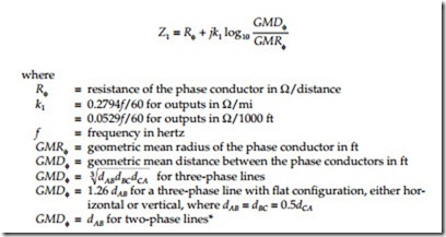
The positive-sequence impedance of overhead lines is
Zero-sequence impedance calculations are more complicated than positive-sequence calculations. Carson’s equations are the most common way to account for the ground return path in impedance calculations of overhead circuits. Carson (1926) derived an expression including the earth return path. We’ll use a simplification of Carson’s equations; it includes the following assumptions (Smith, 1980)
• Since distribution lines are relatively short, the height-dependent terms in Carson’s full model are small, so we neglect them.
• The multigrounded neutral is perfectly coupled to the earth (this has some drawbacks for certain calculations as discussed in Chapter 13).
• End effects are neglected.
• The current at the sending end equals that at the receiving end (no leakage currents).
• All phase conductors have the same size conductor.
• The ground is infinite and has uniform resistivity.
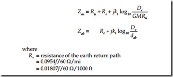
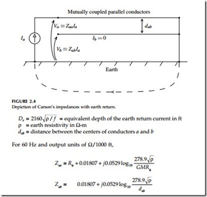
Consider the circuit in Figure 2.4; current flows in conductor a and returns through the earth. The voltage on conductor a equals the current times Zaa, which is the self-impedance with an earth return path. The current in con- ductor a induces a voltage drop along conductor b equaling the phase-a current times Zab, which is the mutual impedance with an earth return path. These two impedances are found (Smith, 1980) with
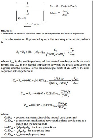
These equations lead to different formulations for the zero-sequence impedance of circuits depending on the grounding configuration. They are also useful in their own right in many circumstances. Single-phase circuits with a phase and a neutral are often easier to analyze using these equations rather than using sequence components. Consider a single-phase circuit that is perfectly grounded with a current of IA in the phase conductor. As Figure 2.5 shows, we can find the neutral current as a function of the mutual impedance between the two conductors divided by the self-impedance of the neutral conductor.
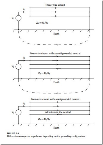
Now, let’s look at the zero-sequence impedances — these change depend- ing on grounding configuration. Figure 2.6 shows the configurations that we will consider.
A three-wire overhead line has a zero-sequence impedance of (Smith, 1980):
A special case is for a four-wire unigrounded circuit where the return current stays in the neutral, which has a zero-sequence impedance of (Ender et al., 1960)
This is for a four-wire unigrounded circuit where there are no connections between the neutral conductor and earth. We can also use this as an approx- imation for a multigrounded neutral line that is very poorly grounded. Remember that the equation given above for a multigrounded circuit assumes perfect grounding. For some calculations, that is not accurate. This is the opposite extreme, which is appropriate for some calculations. Lat (1990) used this as one approach to estimating the worst-case overvoltage on unfaulted phases during a line-to-ground fault.
So, what does all of this mean? Some of the major effects are:
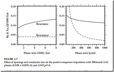
• Conductor size — Mainly affects resistance — larger conductors have lower positive-sequence resistance. Positive-sequence reactance also lowers with larger conductor size, but since it changes with the logarithm of conductor radius, changes are small.
• Conductor spacings — Increasing spacing (higher GMDf) increases Z1.
Increasing spacing reduces Z0. Both of these changes with spacing
are modest given the logarithmic effect.
• Neutral — Adding the neutral always reduces the total zero-sequence impedance, |Z0|. Adding a neutral always reduces the reactive por- tion of this impedance. But adding a neutral may increase or may decrease the resistive portion of Z0. Adding a small neutral with high resistance increases the resistance component of Z0.
• Neutral spacing — Moving the neutral closer to the phase conductors reduces the zero-sequence impedance (but may increase the resistive portion, depending on the size of the neutral).
• Earth resistivity — The earth resistivity does not change the earth return resistance (Re only depends on frequency). The current spreads to wider areas of the earth in high-resistivity soil. Earth resistivity does change the reactance. Higher earth resistivities force current deeper into the ground (larger De), raising the reactance.
• Grounding — The positive-sequence impedance Z1 stays the same regardless of the grounding, whether four-wire multigrounded, ungrounded, or unigrounded.
• Negative sequence — Equals the positive-sequence impedance.
Figure 2.7 and Figure 2.8 show the effects of various parameters on the positive and zero-sequence impedances. Many of the outputs are not particularly sensitive to changes in the inputs. Since many parameters are functions of the logarithm of the variable, major changes induce only small changes in the impedance.
When do we need more accuracy or more sophistication? For power flows, fault calculations, voltage flicker calculations, and voltage sag analysis, we normally don’t need more sophistication. For switching surges, lightning, or other higher frequency transient analysis, we normally need more sophis- ticated line models.
Most unbalanced calculations can be done with this approach, but some cases require more sophistication. Distribution lines and most lower-voltage subtransmission lines are not transposed. On some long circuits, even with balanced loading, the unbalanced impedances between phases creates volt- age unbalance.
Related posts:
Incoming search terms:
- Calculating chickadee conductor impedance
- circuit model for single phase to neutral overhead line
- how to calculate positive and zero sequence from give self and mutual impedances
- simplified line impedance calculations
- overhead lines impedance calculations
- overhead line impedance calculator
- how to calculate zero sequence resistance of 400kv transmission line
- how to calculate the line impedance
- how to calculate the impedance drop of a transmission line
- Carsons equation line impedance
- single phase zero sequence impedance
