Energy and power
Mechanical energy
According to Newton’s third law of motion, mechanical force causes movement in a straight line, such that the force F (N) accelerates a mass m (kg) with acceleration a (m/s2)
Rotational movement depends in the same way upon torque T (N m) accelerating a moment of inertia J (kg m2) with angular acceleration a (rad/s2)
Movement is often opposed by friction. Friction forces and torques always work against the movement. Friction between dry surfaces has a maximum value, depending on the contact force. Once the driving force exceeds the limiting friction force, the system will move and the friction force says constant. Viscous damping gives a restraining force which increases with the speed. Friction between lubricated surfaces is mainly a viscous effect.
Objects store potential energy when they are lifted up. The stored energy W (J) of a mass m is proportional to the height h (m) above ground level, when the acceleration due to gravity g = 9.81 m/s
Electrical energy
In electrical circuits, electrical potential energy is stored in a capacitance C charged to a voltage V
while kinetic energy is stored in an inductance L carrying a current I
Capacitors and inductors store electrical energy. Resistors dissipate energy and convert it into heat. The power dissipated and lost to the electrical system in a resistor R has already been shown in eqn 2.27.
Electrical and mechanical systems can convert and store energy, but overall the total energy in a system is conserved. The overall energy balance in an electromechanical system can be written as
electrical energy in + mechanical energy in
= electrical energy lost in resistance
+ mechanical energy lost in friction
+ magnetic energy lost in steel core (2.60)
+ increase in stored mechanical energy
+ increase in stored electrical energy
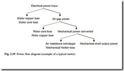
The energy balance is sometimes illustrated in a power flow diagram (Fig. 2.19).
The overall efficiency of a system is the ratio of the useful output power to the total input power, in whatever form
In an ac circuit, the instantaneous power depends on the instantaneous product of volt- age and current. For sinusoidal voltage and current waveforms, the apparent power S (VA) is the product of the rms voltage and the rms current.
When the voltage waveform leads the current waveform by an angle f, the average, active or real power P (W) is
The real power is converted mainly into heat or mechanical power. In addition there is an oscillating flow of instantaneous power, which is stored and then released each
cycle by the capacitance and inductance in the circuit. This imaginary or reactive power Q (VAr) is given by
By convention an inductive circuit (where the current lags the voltage) absorbs VAr, while a capacitive circuit (where the current leads the voltage) acts as a source of VAr. The relationship between S, P and Q is
In a three-phase circuit, the total real power is the sum of the power flowing into each phase. For a balanced three-phase circuit with phase-neutral voltage VP and phase cur- rent IP the total power is the sum of the powers in each phase
Similar relations hold for the reactive and apparent power.
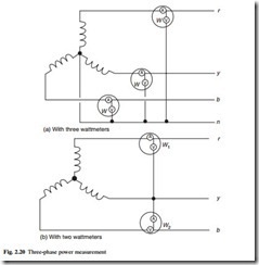
The power in a three-phase circuit can be measured using three wattmeters, one per phase, and the measurements added together (Fig. 2.20(a)). If it is known that the load is balanced, with equal current and power in each phase, the measurement can be made with just two wattmeters (Fig. 2.20(b)). The total power is then
Per-unit notation
Power systems often involve transformers which step the voltage up or down. Transformers are very efficient, so that the output power from the transformer is only slightly less than the input power. Analysis and design of the circuit is made easier if the circuit values are normalized, such that the normalized values are the same on both sides of the transformers. This is accomplished using the per-unit system. A given section of the power system operates at a certain base voltage VB. Across transformers the voltage steps up or down according to the turns ratio. The base voltage will be different on each side of the transformer. A section of the system is allocated a base apparent power rating or base VA V . AB. This will be the same on both sides of the transformer.
Combining these base quantities gives a base impedance ZB and base current IB.
The base impedance and base current change across a transformer.
All voltages and impedances in the system are normalized using the appropriate base value. The resulting normalized quantities are per-unit values. Once the circuit has been converted to per-unit values, the transformers have no effect on nominal tap position, and can be replaced by their own equivalent per-unit impedance.
The per-unit values are sometimes quoted as per cent values, by multiplying by 100 per cent.
A particular advantage of the per-unit and per cent notation is that the resulting impedances are very similar for equipment of very different sizes.
Energy transformation effects
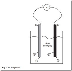
Most electrical energy is generated by electromagnetic induction. However, electricity can be produced by other means. Batteries use electrochemistry to produce low volt- ages. An electrolyte is a solution of chemicals in water such that the chemical separates into positively and negatively charged ions when dissolved. The charged ions react with the conducting electrodes and release energy, as well as give up their charge (Fig. 2.21). A fixed electrode potential is associated with the reaction at each electrode; the difference between the two electrode potentials drives a current around an external circuit. The electrolyte must be sealed into a safe container to make a suitable battery.
‘Dry’ cells use an electrolyte in the form of a gel or thick paste. A primary cell releases electricity as the chemicals react, and the cell is discarded once all the active chemicals have been used up, or the electrodes have become contaminated. A secondary cell uses a reversible chemical reaction, so that it can be recharged to regenerate the active chemicals. The fuel cell is a primary cell which is constructed so that the active chemicals (fuel) pass through the cell, and the cell can be used for long periods by replenishing the chemicals. Large batteries consist of cells connected in series or parallel to increase the output voltage or current. The main types of primary, secondary and fuel cell are described in sections 12.2 to 12.5.
Electricity can be generated directly from heat. When two different materials are used in an electrical circuit, a small electrochemical voltage (contact potential) is generated at the junction. In most circuits these contact potentials cancel out around the circuit and no current flows. However, the junction potential varies with temperature, so that if one junction is at a different temperature from the others, the contact potentials will not cancel out and the net circuit voltage causes current to flow (Seebeck effect). The available voltage is very small, but can be made more useful by connecting many pairs of hot and cold junctions in series. The thermocouple is used mostly for measurement of temperature by this effect, rather than for the generation of electrical power (see section 4.4.1). The efficiency of energy conversion is greater with semiconductor junctions, but metal junctions have a more consistent coefficient and are preferred for accurate measurements. The effect can be reversed with suitable materials, so that passing an electric current around the circuit makes one junction hotter and the other colder (Peltier effect). Such miniature heat pumps are used for cooling small components.
Certain crystalline chemicals are made from charged ions of different sizes. When a voltage is applied across the crystal, the charged ions move slightly towards the side of opposite polarity, causing a small distortion of the crystal. Conversely, applying a force so as to distort the crystal moves the charged ions and generates a voltage. This piezoelectric effect is used to generate high voltages from a small mechanical force, but very little current is available. The use of piezoelectric sensors for the measurement of mechanical pressure and force is described in section 4.2.4. Ferromagnetic materials also distort slightly in a magnetic field. The magnetostrictive effect produces low frequency vibration (hum) in ac machines and transformers.
Electricity can be produced directly from light. The photovoltaic effect occurs when light falls on suitable materials, releasing electrons from the material and generating electricity. The magnitude of the effect is greater with short wavelength light (blue) than long wavelength light (red), and stops altogether beyond a wavelength threshold. Light falling on small photovoltaic cells is used for light measurement, communications and for proximity sensors. On a larger scale, semiconductor solar cells are being made with usable efficiency for power generation.
Light is produced from electricity in incandescent filament bulbs, by heating a wire to a sufficiently high temperature that it glows. Fluorescent lights produce an electrical discharge through a low-pressure gas. The discharge emits ultraviolet radiation, which causes a fluorescent coating on the inside of the tube to glow.


