Thermal Redistributed Modulations Under LVRT
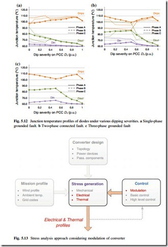
Based on the thermal stress analysis under LVRT, it is found that the thermal distribution of 3L-NPC inverter is quite unequal and inefficient: as the “hottest” power devices, the NPC diodes Dnpc and inner switch Tin have up to 40 K higher junction temperature than the most “cold” device Din. In this section, a series of thermal redistributed modulations for 3L-NPC converter are going to be presented, which aims to achieve a more even junction temperature among different power devices under extreme grid faults. The relevant determining factors for analysis are highlighted in Fig. 5.13, and it can be seen that this section mainly focuses on the electrical and thermal stresses influenced by the modulation strategy of the wind power converter.
Basic Idea
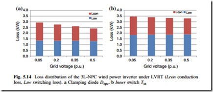
The loss distribution of the most stressed clamping diode Dnpc and inner switch Tin
respectively, where only three-phase balanced grid fault condition is assumed for simplicity. Referring to the switching process of the 3L-NPC converter [9], the losses in Dnpc and Tin will be effectively relieved by reducing the dwelling time of zero voltage level (reduced conduction loss) or reducing the commutations involving zero voltage level (reduced switching loss).
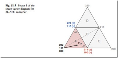
When implementing the space vector modulation for 3L-NPC inverter, the reference vector under extreme LVRT is mainly located in the inner hexagon of space vector diagram. In this special area, there are one or two switching redun- dancies for each state vector, and it is possible that some of the switching redundancies could modify the loss distribution and achieve better thermal distribution for the 3L-NPC wind power inverter under LVRT operation.
For simplicity, the sequence generation method is demonstrated only based on sector I (0°–60°) in the space vector diagram for 3L-NPC converter. The detailed information of sector I is shown in Fig. 5.15. As mentioned before, the voltage reference vector Vref in this sector mainly locates in region A under extreme LVRT condition. The reference can be synthesized by the three nearest state vectors: one
from the redundant short vector group 211/100 (red), one from the other redundant short vector group 221/110 (blue), and one from the redundant zero vector group 000/111/222 (black). The numbering “2,” “1,” and “0” of the state vectors represent that a certain phase is connected by the converter to the positive DC bus, the neutral point, and the negative DC bus, respectively.
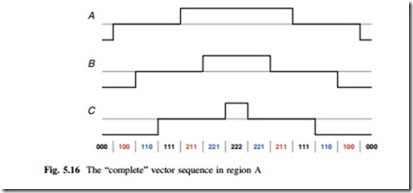
It is interesting that when using all of the state vectors including the redundant ones in region A to synthesize the reference vector Vref, the sequence arrangement is unique if the least switching process and symmetric pulses for each phase are realized, as shown in Fig. 5.16. All of the state vectors in region A are visited without unnecessary switching processes and abrupt voltage level changes.
Therefore, other applicable modulation sequences can be generated by elimi- nating some redundant state vectors in the “complete” vector sequence. However, the sequence generation method must follow two criteria:
i. Atleast one state vector from each of the “three nearest” redundant vector group has to be used in order to synthesize the desired reference voltage.
ii. The state vectors have to be arranged in reverse fashion over one carrier cycle in order to smoothly be connected with the succeeded vector sequence without extra switching processes.
A Group of Modulation Methods
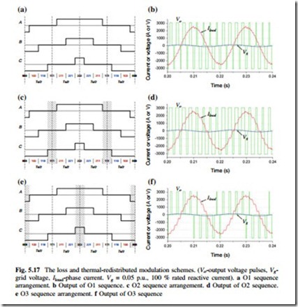
In order to reduce the output time for the zero voltage level of 3L-NPC inverter during LVRT, one effective way is to reduce the activating time for the zero state vector “111” when generating the modulation sequence (because vector 111 outputs zero voltage level for all of the three phases). Figure 5.17a indicates a special modulation sequence, and it is called Optimized sequence 1 (O1) for convenience.
The output time for zero vector 111 in O1 sequence is reduced and partly replaced by the equivalent zero state vectors 000 and 222.
Another direct and basic idea is trying to avoid using the state vector “111” based on the “complete” sequence, as shown in Fig. 5.17b which is called Optimized sequence 2 (O2) for convenience. It can be seen that the zero state vectors 111 are totally replaced by the equivalent state vectors 000 and 222. The output waveforms of the O2 sequence are shown in Fig. 5.17d, in which the widths of both positive and negative output voltage pulses are expanded, compared to the O1 sequence—which means further reduced dwelling time for zero voltage level.
In order to reduce the commutations involving zero voltage level, the third modulation sequence is generated in Fig. 5.17e, which eliminates the zero state vectors 000 and 222, and is called Optimized sequence 3 (O3) for convenience. The
output waveforms of the O3 sequence are shown in Fig. 5.17f, in which there are less output voltage pulses compared to the O1 and O2 sequences—which means reduced commutations and less switching loss in Dnpc and Tin.
It is noticed that because there is redundancy for each of the state vector, all the used vectors in the proposed sequences are arranged within two switching cycles rather than one, as indicated at the bottom of Fig. 5.17a, c, e, respectively. As a result, compared to the normal sequence, the equivalent switching frequency in the proposed sequences is not further increased especially for O1 and O2.
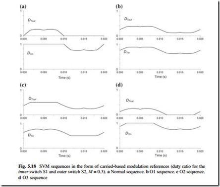
For better understanding the proposed space vector modulation sequences in the form of carried-based modulation, they are transferred to the voltage references/duty ratio for the inner and outer switches of 3L-NPC converter, as shown by DTout and DTin in Fig. 5.18. It can be seen that compared to the normal sequence, the O1 and O2 sequences generally move the level of voltage references, introducing larger duty ratio for the outer switch and smaller duty ratio for the inner switch—which will lead to the longer dwelling time for the positive/negative voltage output and reduce the dwelling time of the zero voltage output. In respect to the O3 sequence, the duty ratio is very similar to the normal sequence but
deviations can be found around the time for zero crossing of voltage reference— which means that the dwelling time for zero voltage output is not significantly reduced. The O3 sequence is very similar to the modulation sequence proposed by [10, 11].
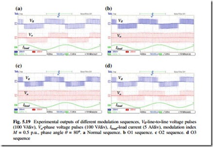
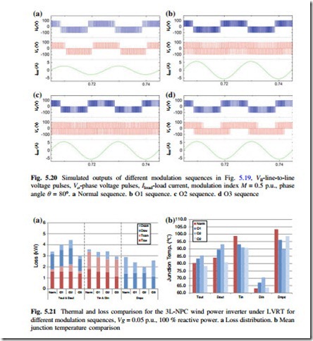
The proposed modulation sequences are also validated on a downscaled experimental setup, as shown in Fig. 5.19, whose detailed parameters are listed in Appendix II, where a special passive RL load is used to emulate the LVRT operation of converter. Based on the same condition of the experimental setup, a series of simulations are also carried out and the results are shown in Fig. 5.20. It can be seen that the experimental results of line-to-line voltage pulses, phase voltage pulses, and load current have good agreement with the simulations.
Loss and Thermal Improvements
The loss distributions of the 3L-NPC wind power converter under LVRT when utilizing the normal and optimized vector sequences are compared in Fig. 5.21a. The comparison of steady-state mean junction temperature distribution is shown in Fig. 5.21b. It can be seen that the optimized sequences O1, O2, and O3 all achieve the loss and thermal redistribution among the power devices, and the stress of Dnpc and Tin can be relieved under LVRT operation. The mean junction temperature
reductions in the most stressed devices Dnpc and Tin are estimated to be up to 12 and 8 K, respectively, when the O2 modulation sequence is applied, while the O3 sequence shows another advantage in reducing the stress in Tout and Dout by 3 and 5 K, respectively.
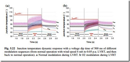
The dynamic thermal performance of 3L-NPC wind power inverter which goes from normal operation to extreme LVRT and then back to normal operation can also be simulated. For simplicity, only the results when applying O2 sequence are indicated and more results can be found in [12]. It can be seen from Fig. 5.22 that the maximum junction temperatures in Dnpc and Tin are both reduced, and more
equal thermal distribution can be achieved compared to the normal modulation. This improvement may contribute to a lifetime extension of the converter according to the important Coffin-Masson lifetime model.
Neutral Point Potential Control and Total Harmonic Distortion In order to analyze the control ability of Neutral Point (NP) potential by the pro- posed modulation sequence, the neutral point current iNP which is the main reason for the DC bus unbalance will be focused.
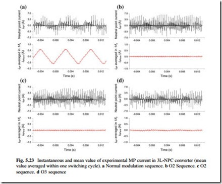
For the proposed three sequences O1, O2, and O3, both of the used short vectors have redundancies, which mean full control freedom for the NP current, and it is possible to achieve zero iNP within one switching cycle under all power factors and applicable modulation indexes. Consequently, the NP potential control ability of all the proposed modulation sequences should be better than the normal SVM sequence. Figure 5.23 indicates the experimental NP current of the 3L-NPC converter when different modulation methods are applied. It is noted that the active NP current control is not active. For clarity, both the instantaneous neutral point current iNP and its switching-cycle-averaged value iNPave are indicated. It can be seen that the iNPave in the proposed modulation sequences O1–O3 are almost eliminated, while the normal modulation sequence has iNPavg which oscillates at 0.2 p.u. amplitude and three times of the fundamental frequency.
Nevertheless, the proposed modulation sequences especially for O2 and O3 have no Total Harmonic Distortion (THD) improvements compared to the normal sequence. This can be also observed from the load current waveforms in Fig. 5.17d, f, where the current distortions in the O2 and O3 sequences are actually more than that in the normal sequence of Fig. 5.17a. However, it is noted that under the LVRT operation, which is an abnormal condition and normally last up to few seconds, the
first control target is to make the grid converter survive when withstanding the grid voltage dips and providing large amount of reactive power support. Therefore, THD is relatively less important performance for the wind power converter under the LVRT.
Based on the similar idea, there are many groups of modulation sequences that can be generated, which are able to modify the thermal distribution of 3L-NPC converter under LVRT operation. More details can be found in Chap. 13.
