Insulation Condition
This refers to the insulation between the windings and ground. High temperatures, age, moisture, and dirt contamination all lead to shortened insulation life. It has been said that if the industry would just use the space heaters available to keep the insulation dry, then doubling the life of our motors would not be out of the question.
The importance of having good electrical insulation systems is obvious. The designs and applications of electrical equipment are almost infinite in their variety, but all units have one common characteristic. For electrical equipment to operate correctly, one of the most important characteristics is that the flow of electricity takes place along well-defined paths or circuits. These paths are normally limited to conductors, either internal or external to the electrical component. It is important that the flow of current be confined to defined conducting paths and not leak from one path to another through materials not intended to become conducting paths. Deterioration of insulation systems can result in an unsafe situation for personnel exposed to the leakage current.
Despite great strides in electrical equipment design in recent years, the weak link in the chain is still the insulation system. When electrical equipment fails, more often than not the fault can be traced to defective insulation. Even though an electric motor is correctly designed and tested prior to installation, there can be no guarantee that a fault in the insulation will not occur at some time in the future.
Many outside influences affect the life of electrical insulation systems. Outside influences include contamination of the insulation surfaces with chemicals from the surrounding atmosphere that attack and destroy the molecular structure, physical damage due to incorrect handling or accidental shock, vibration, and excessive heat from nearby industrial processes. Voltage transients in the conductors inside the insulation, such as surges or spikes caused by VFDs, can lower the dielectric strength to the point of failure. The deterioration occurs in many ways and in many places at the same time. For example, as chemicals and heat change the molecular structure of the insulating materials, they become semi-conductive, allowing more current to be forced through them by voltage resulting in leakage current.
Correctly conducted insulation system testing, analysis of the data collected, and followed by appropriate corrective actions can minimize the possibility of failures. Therefore, the significance of understanding insulation system testing has never been more important. The reader should refer to Chapters 1 and 2 for detail discussion of insulation (dielectric) theory and practice and conducting tests using DC voltage. A brief overview of the subject matter is offered here from the perspective of motor-winding insulation.
Insulation resistance measurements
The insulation system of motor windings is often checked using DC voltage tests. One of the most common test conducted is to measure the insulation resistance of the motor windings using an insulation resistance tester. When testing insulation with DC voltage, the total current drawn is the sum of four different currents: surface leakage, geometric capacitance, conductance, and
absorption.
The surface leakage current is constant over time. Moisture or some other type of partially conductive contamination present in the machine causes a high surface leakage current, i.e., low insulation resistance.
The geometric capacitance current is a reversible component of the measured current on charge or discharge that is due to the geometric capacitance. That is the capacitance as measured with AC of power or higher frequencies. With direct voltage, this current has a very short time constant and does not affect the usual measurement.
The conduction current in well-bonded polyester and epoxy-mica insulation systems is essentially zero unless the insulation has become saturated with moisture. Older insulation systems, such as asphaltic-mica or shellac mica-folium may have a natural and higher conduction due to the conductivity of the adhesive tapes used as backing of the mica.
The absorption current is made of two components: the polarization of the insulation material and the gradual drift of electrons and ions through the insulating material. The polarization current is caused by the reorientation of the insulating material. This material, usually epoxy, polyester, or asphalt tends to change the orientation of their molecules when in the presence of a DC electric field. It normally takes a few minutes of applied voltage for the molecules to be reoriented, and thus for the current-supplied polarizing energy to be reduced to almost zero. The absorption current, which is the second component, is the gradual drift of electrons and ions through the insulating material. These electrons and ions drift until they become trapped at the mica surfaces usually found in motor insulation systems. The positively and negatively charged molecules of an insulation system are shown in Figure 10.19.
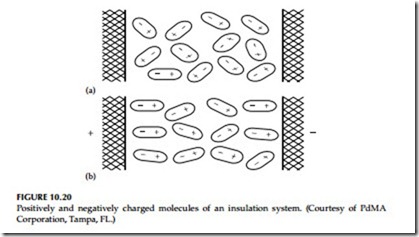
Figure 10.20a shows the random orientation of the insulation’s molecules.
As DC voltage is applied to the insulation, the molecules start to polarize and align, as shown in Figure 10.20b. The energy required to align the molecules, and subsequently reduce the amount of escaping molecules, is known as absorption current. Since absorption current is a property of the insulation material and the winding temperature, a specific absorption current is neither good nor bad. The absorption currents will vary from different insulating material.
Prior to 1970, older thermoplastic materials used for motor winding insulation were typically asphalt or shellac, which has a higher absorption current.
After 1970, the shift was made to thermosetting polyester or epoxy-bonded insulating material, which significantly decreased the absorption current.
Nonetheless, this does not mean that the more modern insulating materials are better because they have less absorption current. The amount of applied voltage must be appropriate to the nameplate voltage and the basic insulation condition. This is particularly important in small, low-voltage machines
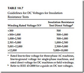
where there is only a single layer of insulation. If test voltages are too high, the applied voltage may over stress the insulation. See Table 10.7 for recommended voltage application.
Also, the capacitance value of insulation may be measured to reflect on the cleanliness of the windings. A buildup of contamination on the surface of the windings results in higher capacitance readings. With a buildup of contamination on the insulation surface, dirty windings produce higher capacitance values than clean ones do. Over time, capacitance values steadily increased indicating an accumulation of dirt and that cleaning is necessary.
Effects of contamination
There are many factors that can affect insulation resistance. The surface leakage current is dependant upon foreign matters, such as oil and carbon dust on the winding surfaces outside the stator slot. The surface leakage current may be significantly higher on large turbine generator rotors and DC machines, which have relatively large-exposed creepage surfaces. Dust and salts on insulation surfaces, which are ordinarily nonconductive when dry, may become partially conductive when exposed to moisture or oil, and this will cause increased surface leakage current and lower insulation resistance. The reason a motor’s capacitance increases with contamination is because of how a capacitor works. Any two conducting materials, called plates, separated from each other by a dielectric material, form a capacitor. A dielectric material is anything that is unable to conduct direct electric current. A cable or motor winding surrounded by insulation provides one conductor and the dielectric material. The second plate is formed by the stator core and motor casing iron. It is this second plate that is increased in plate size as contamination builds up.
Effects of temperature
A higher temperature affects the resistance of both the insulation and conductor. There is a term called temperature coefficient (KT). A material has either a positive or negative KT. If the material has a positive KT, then with added heat the resistance readings will increase. Inversely, if a material has a negative KT, then the resistance readings will decrease with higher temperature. In metals, i.e., the magnetic wire of the stator, higher temperature introduces greater thermal agitation and reduces the movements of free electrons. Because of this reduction in free movement, the resistance readings will increase with added heat and therefore the conductor has a positive KT. However, in insulation, the added heat supplies thermal energy, which frees additional charge carriers and reduces the resistance reading. Therefore, an increase in temperature on insulation reduces the resistance and it is said to have a negative KT. This higher temperature affects every current except the geometric capacitive current.
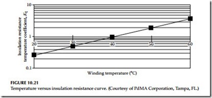
The recommended method of obtaining data for an insulation resistance versus winding temperature curve is by making measurements at several winding temperatures, all above the dew point, and plotting the results on a semilogarithmic scale. Since this type of temperature coefficient plotting is usually not feasible, it is recommended to avoid the effects of temperature in trend analysis, subsequent tests should be conducted when the winding is near the same temperature as the previous tests. Otherwise the insulation test values should be corrected to a common base temperature of 40°C for trend analysis.
Therefore, resistance-to-ground readings must be temperature corrected for trending and comparison purposes. Temperature correction of the reading is required because the temperature of the insulation system under test may vary depending on operating conditions prior to testing, atmospheric conditions, or ambient temperature. Insulation material has a negative temperature coefficient, which means that the resistance characteristics vary inversely with temperature. In the test setup screen of a standard test, the temperature of the windings will have an effect on the measurement. The measured megohm value is then adjusted to a temperature correction to 40°C. The result is the
corrected megohm readings. To accurately trend resistance reading for a motor over time, keep the test voltage and duration of applied voltage constant.
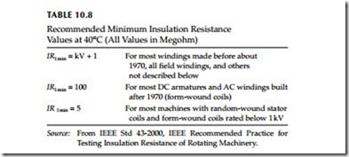
The temperature-corrected megohm readings should be recorded and graphed for comparison over time. If a downward trend is observed, look for dirt or moisture. A single reading will not have much meaning in regards to the overall health of the insulation system; a reading as low as 5 MΩ may be accept- able if related to a low-voltage application. See Table 10.8 for recommended minimum insulation resistance. Also, refer to Section 2.10.1 in Chapter 2 for additional discussion on recommended minimum insulation resistance values. This is important because dirt and contamination reduce the motor’s ability to dissipate heat generated by its own operation, resulting in premature aging of the insulation system. A general rule of thumb is that a motor’s life decreases by 50% for every 10°C increase in operating temperature above the design temperature of the insulation system. Heat raises the resistance of conductor materials and reduces the insulation resistance of the winding insulation, and therefore breaks down the insulation. These factors accelerate the development of cracks in the insulation, providing paths for unwanted current to flow to ground. The effects from temperature to insulation resistance are shown in Figure 10.21.
Polarization index and dielectric absorption
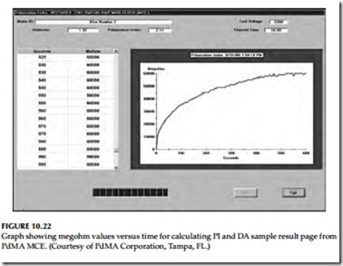
The polarization index (PI) and dielectric absorption (DA) tests are performed with a megohmmeter on a deenergized motor. It is not necessary to perform a DA test if a PI test is performed. Refer to Sections 2.3.1.2 and 2.3.1.3 for description of DA and PI tests. The purpose of the PI test is to determine whether or not a motor’s insulation system is suitable for continued service. The PI test is not limited to AC induction motors only. It also applies to wound-rotor motors, salient pole machines, and certain DC fields. The DC field would have to have conductors that are fully encapsulated in insulation. Therefore, the PI test can be a worthwhile test for multiple type machines. When performing a PI test, it is not necessary to correct for temperature. Since the machine temperature does not change appreciably between the 1 min and the 10 min readings, the effect of temperature on the PI is usually small. However, if the motor recently shut down and a PI test is performed, the results may be a substantial increase in insulation resistance. This would result in an unusually high PI, at which point additional testing should be performed once the windings have cooled to 40°C or lower. Refer to Table 2.14 in Chapter 2 for Interpretation of PI and DA data. Excellent results should indicate a PI ratio of 2–4, achieve higher than minimal insulation resistance values, and should be a nonsporadic rise in the megohm readings as shown in Figure 10.22.
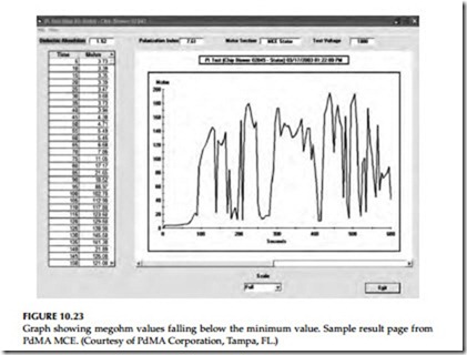
Erratic insulation resistance values occurring at anytime during the test are indicative of short-term current transients. These may be due to contamination or moisture. It is important to know how low the insulation resistance values fall to in order to grade the insulation. For example, the IEEE standards
recommend minimum insulation resistance value of 100 MΩ for form-wound coils. Figure 10.23 shows insulation resistance values dipping below the suggested minimum value of 100 MΩ for a form-wound coil. The PI and DA tests can be both used as go–no-go, based on the minimum insulation resistance readings.
The PI value of greater than 4 does not necessarily mean that the health of the insulation system is good. The higher PI value may indicate other problems with the insulation system, such as being too dry and brittle indicating that it has lost some or all of its mechanical properties. According to the EASA’s principles of large AC motors, it states that PI ratios of greater than 5 should be considered the result of dry or brittle insulation. This may be because of age of the insulation or operating the motor at higher than designed temperatures as shown in Figure 10.24. A very dry or brittle insulation may indicate good insulation resistance but it may not have the necessary dielectric strength and mechanical pliability.
