Predictive Maintenance Guide on Motors and Variable Frequency Drives
Electrical maintenance personnel have for years been limited to trouble- shooting motors with no more than a multimeter and an insulation resistance tester (megohmeter). The insulation resistance tester unfortunately does not provide enough information to allow most technicians to feel totally confident in determining whether or not an electrical problem exists or not. The troubleshooting of motors has become more difficult in recent years since many motors today are coupled to variable frequency drives (VFDs). The VFD itself in many cases can cause problems in the motor since it produces harmonics that pollute the power supply to the motor. At the end of this section, a discussion is offered on VFD and its interaction with the motor to help the reader understand its impact on a motor.
There has always been an on-going struggle to utilize technology to iden- tify problems in motors. Recently technologies, such as vibration analysis has been developed to aid in the identification of problems in motors. When vibration analysis shows a two times line frequency (2 FL) spike, it is assumed that it must mean an electrical problem. However, it must be kept in perspective that there are many other variables that may be responsible for producing a 2 FL spike; therefore, removing a motor from service for an electrical repair due only to a high 2 FL could be a mistake, possibly an expensive one. Also, just measuring the insulation resistance of motor windings may not be enough to say that the motor is fine for continued service or it can be put back in service after it has tripped off-line. The fact is numerous reasons can exist which causes a motor to trip that will not be seen by an insulation test,
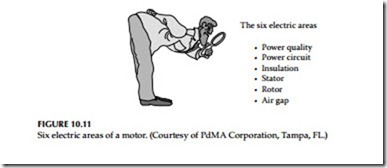
such as a turn-to-turn short. Breakdown in the insulation between individual turns of a winding can occur inside a stator slot or at the end turn and be completely isolated from ground. Phase-to-phase shorts can occur the same way. If these faults are left unattended, they can result in rapid deterioration of the winding, potentially ending in a complete motor replacement. Restarting of a motor that has tripped should be considered only after these faults have been ruled out. Troubleshooting an electric motor that is suspected to have an electrical problem requires checking the insulation system as well other components in the motor. To confidently assess the electrical condition of a motor and ensure that it will run reliably, there are six electrical areas in a motor analysis that must be looked at during the troubleshooting effort. Missing any of these areas could result in missing the problem and not having enough information to make a correct decision. The six areas are illustrated in the Figure 10.11.
Predictive technologies and tools are available today to troubleshoot and test these areas of interest. PdMA Corporation is just one of the several entities that have developed technologies and tools for diagnosing motor problems. PdMA offers two instruments that go beyond the conventional insulation resistance (megohmmeter) tester and multimeter for predictive maintenance and troubleshooting. These instruments are EMAX and MCE. How they can be used to help diagnose motor problems in the six electrical areas of a motor and how to evaluate these areas are discussed next.
Power Quality
Power quality has recently been thrust in the forefront due to the application of AC and DC drives, as well as other nonlinear loads. The variable frequency drives (VFDs) and other nonlinear loads can significantly increase the distortion levels of voltage and current. How can this distortion be minimized? What equipment is required, and is the concern purely financial or is equipment at risk? Power quality problems as it pertains to motor health involve voltage and current harmonic distortion, voltage spikes, voltage unbalance or imbalance and PF. The basic principle that ties them all together including thermal heating are discussed in this guide from the perspective of motor reliability and troubleshooting.
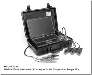
By developing a methodical step-by-step process, power analysis (PA) tests using a power quality analyzer, such as PdMA’s EMAX shown in Figure 10.12, can be used to get information on quality of the power supply being delivered to the motor. These test results can quickly be used to assess three of the six areas listed above. These areas are derived from the most common electrically related motor failures in an industrial environment. This discussion focuses primarily on the quality of the power supply to the motor, followed by a recommended process on how to evaluate the data recorded during a PA capture.
The EMAX is a dynamic tester that collects data while the motor is operating. This information can be used to evaluate incoming power quality, motor efficiency, rotor, stator, air gap, and power circuit conditions. It simultaneously collects all three phases of current and voltage to provide spectral and digital data in the areas of power, motor current, signature analysis, efficiency, crest factor (CF), total harmonic distortion (THD), sequence data, PF, impedance, current, and voltage.
Power quality refers to the condition of the voltage and current signals. Single- and three-phase nonlinear loads, VFDs, switch-mode power supplies, starting and stopping of large inductive loads, voltage spikes, and the like that can cause poor power quality. These influences can cause excessive harmonics on the electrical distribution system, which can result in overheat- ing of the insulation system and other undesirable effects on the electrical distribution equipment. The term “power quality” is used for defining the quality of power supplied to the motor to do its job. But what is being actually
evaluated is the quality of the voltage that is being supplied to the motor circuit. The power supply system can only control the quality of the voltage; it has no control over the currents that a particular load might draw.
PA test allows a technician to take a power quality snapshot in order to see the condition of the voltage signal and evaluate the effect it will have on the motor. The actual sample time for the simultaneous measurement of the three voltage and current phases takes 0.17 s or less. From this snap- shot, the technician focuses primarily on the three phase-to-phase voltages of the power delivered to the motor and determines what effect they are having on motor performance.
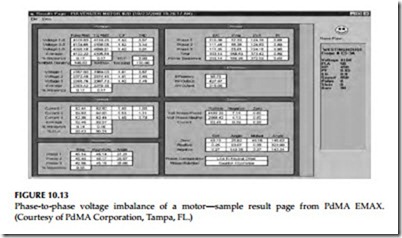
Data used to evaluate power quality is located in the phase-to-phase volt- age section of the results page as is shown in Figure 10.13. In Figure 10.13, the result page shows among other data the input power to the motor, fundamental root mean square (rms), total rms, CF, and THD for each of the phase- to-phase voltages. The average voltage and percent imbalance are also listed. Additionally, recommended NEMA derating factors are provided for both phase-to-phase voltage imbalance and harmonic voltage factor (HVF).
The motor, or for that matter any three-phase machine, is a symmetrical device and is designed to operate on three-phase balanced sinusoidal volt- ages. When line voltages applied to a motor are not equal, negative sequence currents are introduced into the motor windings. The negative sequence cur- rents flow in the windings of the motor in the opposite direction to the normal (positive sequence) currents. Therefore, these negative sequence currents produce an air gap flux that rotates in opposite direction to the rotation of the motor. This reduces the net motor torque, affecting its operation and increasing the temperature rise of the motor.
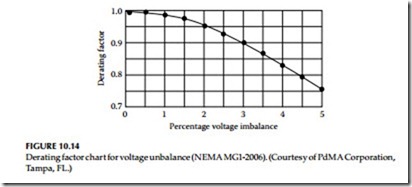
NEMA standard MG1-2006 provides a recommended derating factor based on percent voltage imbalance (Figure 10.14). The usual recommendation is to
not run a motor when the voltage imbalance is greater than 5% (per NEMA MG-1). For a given phase-to-phase voltage imbalance, rated horsepower of an induction motor should be multiplied by the derating factor in accordance with the NEMA MG1-2006 recommendation. If the load on the motor exceeds this derated value, take steps to correct the imbalance, or reduce the load on the motor. Running the motor with the imbalanced voltage will cause exces- sive temperature rise in the windings and damage the insulation.
Terminal Voltage
Terminal voltage has a major effect on motor performance. The effect of low voltage on electric motors is well known and understood; however, the effect of high voltage on motors is often misunderstood. The effects of low and high terminal voltages are discussed next.
Effects of low voltage
When a motor is operated below nameplate rated voltage, some of the motor’s characteristics will change slightly and other characteristics more dramatically. To drive a fixed mechanical load, a motor must draw a fixed amount of power from the circuit to produce the necessary torque to drive the load. The amount of power is roughly related to the voltage times current. So with a lower voltage, there will be a rise in current to maintain the required power.
In terms of torque, the torque produce by the motor is proportional to the square of the voltage. For example, if the voltage to the motor is reduced by 10%, the torque will be reduced by 19%. This in itself is not alarming, unless the torque delivered by the motor is less than the torque required by the fixed load. In order to produce the necessary torque the motor will draw more current, therefore rise in current may exceed the nameplate current rating of the motor. When this happens the buildup of heat within the motor will damage the insulation system.
Aside from the possibility of overtemperature and shortened insulation life, other important effects on the motor’s performance need to be under-stood. Starting, pull-up, and pull-out torque of induction motors all change based on the applied voltage squared. Thus, a 10% reduction from nameplate voltage (100%–90%) would reduce the starting, pull-up, and pull-out torque to 81%. At 80% terminal voltage, the motor would produce 64% torque of the nameplate values. Clearly, it would be difficult to start those hard-to-start loads under such conditions. Similarly, the motor’s pull-out torque will be much lower than during normal voltage conditions.
Effects of high voltage
A common misconception is that high voltage tends to reduce current draw on a motor, since low voltage increases the current. This is not always the case.
High voltage on a motor tends to push the magnetic portion of the motor into saturation. This causes the motor to draw excessive current in an effort to magnetize the iron beyond the point to which it can easily be magnetized.
Generally, motors will tolerate a certain change above nameplate voltage; however, extremes above this value will cause the amperage to go up with a corresponding increase in heating and a shortening of motor life. For example, motors are generally designed to operate satisfactorily with a band of ±10% in accordance with NEMA standards. Even though this is the so-called tolerance band, the best performance would be at rated terminal voltage. Operation at the ends of this band would put unnecessary stress on the motor.
These tolerance bands are in existence not to set a standard that can be used all the time, but rather to set a range that can be used to accommodate the normal hour-to-hour swings in-plant voltage. Continuous operation at either the low or high end of the band will shorten the life of the motor.
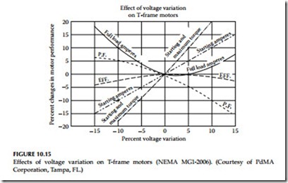
The graph shown in Figure 10.15 is widely used to illustrate the general effects of high and low voltage on the performance of T-frame motors. It is acceptable to show general effects, but remember these effects will change slightly from one motor design to another. High voltages will always tend to Effect of voltage variation on T-frame motors
reduce PF and increase losses in the system, which results in higher operating cost for the equipment and the system. The following guidelines are pro- vided for assistance in evaluating the voltage of a motor circuit:
• Small motors tend to be more sensitive to overvoltage and saturation than large motors
• U-frame motors are less sensitive to overvoltage than T frames
• Premium/high efficiency motors are less sensitive to overvoltage than standard efficiency motors
• Overvoltage can drive up amperage and temperature even on lightly loaded motors; thus, motor life can be shortened by high voltage
• Full-load efficiency drops with either high or low voltage
• PF improves with lower voltage and drops sharply with high voltage
• Inrush current goes up with higher voltage
Simply put, the best life and efficient operation of electric motors occurs when motors are operated at voltage as close to nameplate ratings as possible.
Harmonics
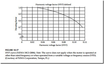
The presence of harmonic distortion in the applied voltage to a motor will both increase electrical losses and decrease efficiency. These losses will increase motor temperature, resulting in even further losses. High harmonics can result in a temperature rise in motor temperature. NEMA MG1-2006 provides a chart for recommended harmonic derating factor known as HVF to aid in evaluating the harmonic voltage effects on the motor’s performance.
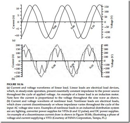
Figure 10.16a shows sinusoidal current and voltage waveforms of a linear load such as a motor. Figure 10.16b shows the nonsinusodial current and voltage waveforms of nonlinear load, such as drawn by a VFD.
When performing PA testing of motor circuits, the power analyzer, such as EMAX, samples the applied voltage signal. It analyzes the voltage waveform, identifies the fundamental frequency and all harmonics present and their percent of the waveform. With this information the HVF is calculated and, if required, recommended derating per NEMA guidelines is provided. The HVF derating curve is shown in Figure 10.17.
There is usually no need to derate motors if the voltage distortion remains within Institute of Electrical and Electronic Engineers (IEEE) Standard 519- 1992 limits of 5% THD and 3% for any individual harmonic. Excessive heating problems begin when the voltage distortion reaches 8%–10% and higher.
Such distortion should be corrected for long motor life.
The PA test, i.e., snap shot of power quality, provides a wealth of detailed information for identifying the power quality being delivered to the motor in a distribution system. In addition, this simple to perform test also provides the data required for detailed evaluation of motor circuits that utilize VFDs.
Phase-to-phase voltage, harmonic distortion, bus voltage, and THD have an effect on the performance and condition of a motor.
Power Circuit
The power circuit refers to all the conductors and connections that exist from the point at which the testing starts through to the connections at the motor. This can include circuit breakers, fuses, contactors, overloads, disconnects, and lug connections. A 1994 demonstration project on industrial power distribution systems found that connectors and conductors were the source of 46% of the faults reducing motor efficiency. When evaluating the condition of a motor, it is a good practice to use as many technologies as possible. The anomalies in a power circuit and how to identify them are discussed next.
Power circuit refers to all the conductors and connections that exist from the power supply bus to the connections at the motor. This can include circuit breakers, fuses, contactors, overloads, disconnects, and lug connections. Many times a motor, although initially in perfect health, is installed into a faulty power circuit. This causes problems like voltage imbalances, current imbalances, etc. As these problems become more severe, providing the
same horsepower output from the motor requires more current, causing temperatures to increase and insulation damage to occur. The PA test as dis- cussed under power quality is performed on energized AC induction, AC synchronous, AC wound-rotor motors, and motors being powered by VFDs. The PA test indicates anomalies in the power circuit, power quality, and the stator fault zones.
High resistance connections in the power circuit result in unbalanced terminal voltages at the motor. The consequences of the unbalanced terminal voltage are overheating of the components adjacent to the high resistance connection, loss of torque, other phases drawing additional current to compensate, over- heating of the insulation system, and a decrease in motor efficiency. Voltage imbalances will cause the motor to draw more current in order to perform the required work. Therefore, this could lead to premature single-phasing or motor burn out resulting in shutdown of a process due to the failed motor.
The values from the PA test that are used to evaluate the health of the power circuit are: phase-to-phase voltage, phase-to-phase current, and their respective imbalances. These measured values are recorded and compared against industry standards. An unbalanced power delivery not only causes a voltage imbalance but also causes a much higher percent current imbalance. Some rules of thumb to apply when troubleshooting the power circuit are listed next.
• A 1% voltage imbalance can result in a 6%–7% current imbalance, according to the Electrical Apparatus Service Association.
• A 3.5% voltage imbalance can raise winding temperatures by 25%, according to the Electrical Power Research Institute.
• A 10°C increase in winding temperature (above design) can result in a 50% reduction of motor life.
Phase voltage unbalance causes three-phase motors to run at temperatures greater than their published ratings. This excessive heating is due mainly to negative sequence currents attempting to cause the motor to turn in a direction opposite to its normal rotation. These higher temperatures soon result in degradation of the motor insulation and shortened motor life. The percent increase in temperature of the highest current winding is approximately two times the square of the voltage unbalance. For example, a 3% voltage unbalance will cause a temperature rise of about 18%. The greater the unbalance, the higher the motor winding temperature and the sooner the insulation will fail. NEMA standards recommend a maximum voltage unbalance of 1% without derating the motor. The motor can be derated down to 75% for a maximum of a 5% voltage unbalance. If the voltage unbalance exceeds 5%, it is recommended that the motor not be operated.
The easiest way to test a power circuit is using the PA test while the motor is under normal operating condition. A current imbalance is a possible indication of a high resistance connection. However, a voltage as well as a current imbalance is a better indicator. What determines whether both imbalances are present in the event of a high resistance connection is the test location.
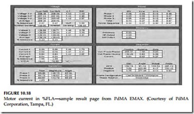
Both voltage and current imbalances are not a requirement in the event of a fault in the power circuit. There can be many different reasons to look for a high resistance connection, a power circuit component failure, or an imbalance that points to another fault zone. Trending power circuit anomalies is most effective at similar loads. Higher loads may result in the fault being more obvious due to the stresses being greater at higher loads. The easiest way to verify the current draw of a motor is by looking at the percent full- load amperes (% FLA) in the current section on the results page of the power analyzer as shown in Figure 10.18.
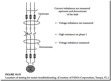
As mentioned earlier, a current imbalance is a possible indicator of a power circuit anomaly. This is because the location of the anomaly in reference to
the voltage test leads will show different imbalances. However, measured current values are consistent regardless of test location. Figure 10.19 shows how voltage readings can change based on test location. If the test is being performed upstream of the anomaly, then there will only be a current imbalance, and if the test is downstream, there will be both a current and voltage imbalance.
Loads using three-phase power sources are subject to loss of one of the three phases from the power distribution system. This condition is known as single-phasing of the primary power supply system. The loss of one phase, or leg, of a three-phase line causes voltages to become unbalanced on the secondary distribution power system, thereby causing serious problems for motors. The motor windings will overheat due primarily to the flow of negative sequence currents, a condition that exists anytime there is a phase volt- age imbalance. The loss of a phase also inhibits the motor’s ability to operate at its rated horsepower.
In conclusion, a high resistance connection results in voltage and current imbalances, which reduces the horsepower rating significantly. When a good motor is installed into a faulty power circuit, it causes problems with power imbalances, as well as, negative sequence currents. As the problems become more severe, the horsepower rating of the motor drops causing temperatures to increase resulting in overheating of adjacent components, damage to the rotor, stator, insulation, shortened motor life, reduced motor efficiency, motor failure, or fire. While damage to the rotor, stator, or insulation might be symptoms of a problem; the root cause still lies with the power circuit.
Replacing the motor without fixing the high resistance connection causes the failure cycle to begin again.
