Pneumatic governors
Pneumatic, or flap valve, governors are less expensive than centrifugal governors and more amenable to repair. The velocity of air moving through the intake manifold is a function of piston speed. The faster the engine runs, the greater the velocity. Pneumatic governors sense this velocity as vacuum developed by a venturi mounted on the air intake.
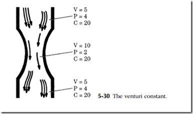
The venturi restricts the flow of air and, so doing, reduces its pressure. This relation- ship has a constant of 20, as shown in Fig. 5-30. If we use consistent terms and multiply pressure times velocity at any point in the venturi, the answer is always 20, or something approximating that number. Nor need the venturi be the sort of streamlined restriction shown in the drawing; any impediment accelerates air flow and reduces its pressure.
Pneumatic governors, while by no means the state of the art, are still encoun- tered on marine and industrial engines. The example discussed below is one of the most complex.
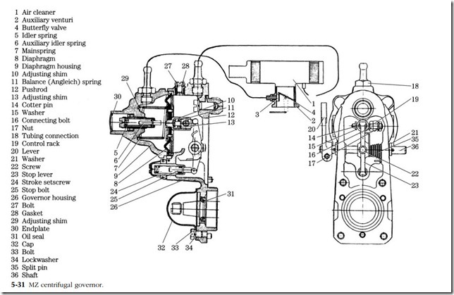
This unit, shown in cross-section in Fig. 5-31, uses a flap, or butterfly, valve (4) as a variable venturi. A tube bleeds vacuum from the edge of the valve to the left or low- pressure side of the diaphragm housing. A second tube brings filtered air at atmos- pheric pressure to the right side of the housing. The spring-loaded diaphragm (8) separates these two halves of the housing and connects to the fuel rack.
The flap valve is free to pivot in response to incoming air velocity. At low engine speeds the valve positions itself as shown in the drawing. All air entering the engine must accelerate and squeeze past the obstruction created by the edge of the valve and the vacuum-line connection. The diaphragm responds to the resulting depression by moving toward the left, or low-pressure, side of the housing. Fuel delivery is reduced. If the engine decelerates as when encountering a load, vacuum drops and the diaphragm shifts toward the right to increase fuel flow.
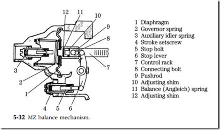
At wide-open throttle, the velocity of incoming air pivots the flap valve full open. Sensing the low level of vacuum, the diaphragm shifts to the right, extending the rack The governor also includes the mechanism shown in Fig. 5-32 that reduces fuel delivery at idle. As the diaphragm moves to its extreme leftward position, it brings
the stop lever (6) to bear against the stop bolt (5). This action compresses the balance spring (11) and displaces the rack (7) toward the no-fuel position. As engine speed increases, the diaphragm moves to the right. The balance spring mechanism moves with it, away from the stop lever. Once clear of the lever, the spring has nothing to react against and is out of the circuit.
Service
The leather diaphragm should hold 500 mm/H2O of vacuum with a leak-down rate of no more than 2 mm/sec. It should be flexible enough to collapse of its own weight when held by the rim. Nissan dealers can supply the special diaphragm oil required to soften the leather.
A screw under the circular end cover reacts with the auxiliary idle spring (3) to set the idle speed. Tightening the screw moves the rack to the right to increase fuel delivery and idle rpm. But the effect extends to all engine speeds (Fig. 5-33). Fuel delivery for best idle over-fuels the engine at high speed and, conversely, a setting that gives best fuel economy at speed, costs low-end power. The adjustment is a compromise.
Other adjustments require a test fixture available to dealer mechanics. For example, the stroke adjustment, shown at 4 in Fig. 5-32, is made to factory specifications with the diaphragm chamber evacuated and the pump turning 500 rpm. To further complicate matters, balance-spring adjustment must be done by comparing its action with a known good unit.


