Measurements and instrumentation
Introduction
Definition of terms
Measured variable and process variable are both terms for the physical quantity that is to be measured. The measured value is the actual value which is measured or recorded, in engineering units (e.g. the level is 1252 mm).
A primary element or sensor is the device which converts the measured value into a form suitable for further conversion into an instrumentation signal. An orifice plate is a typical sensor. A transducer is a device which converts a signal from one quantity to another (e.g. a Pt100 temperature transducer converts a temperature to a resistance). A transmitter is a transducer which gives a standard instrumentation signal (e.g. 4–20 mA) as an output signal.
Range, accuracy and error
Measuring span, measuring interval and range are terms which describe the difference between the lower and upper limits that can be measured. Turndown is the ratio between the upper limit and the lower limits where the specified accuracy can be obtained.
Error is a measurement of the difference between the measured value and the true value and accuracy is the maximum error which can occur between the process variable and the measured value when the transducer is operating under specified condi- tions. Error can be expressed in many ways. The commonest are absolute value, as a percentage of the actual value, or as a percentage of full scale.
Many devices have an inherent coarseness in their measuring capabilities. A wire wound potentiometer, for example, can only change its resistance in small steps. Resolution is used to define the smallest step in which a reading can be made.
In many applications, the accuracy of a measurement is less important than its consistency. Repeatability is defined as the difference in readings obtained when the same measuring point is approached several times from the same direction.
Hysteresis occurs when the measured value depends on the direction of approach. Mechanical backlash and stiction are common causes of hysteresis.
The accuracy of a transducer will be adversely affected by environmental changes, particularly temperature cycling, and will degrade with time. Both of these effects will be seen as a zero shift or a change of sensitivity (known as a span error).
Dynamic effects
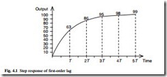
A sensor cannot respond instantly to changes in the measured process variable. Commonly the sensor will change as a first-order lag with time constant T, as shown in Fig. 4.1.
For a step change in input, the output reaches 63 per cent of the final value in time T, and it follows that a significant delay may occur for a dynamically changing input signal.
A second order response occurs when the transducer is analogous to a mechanical spring/viscous damper. The step response depends on both the damping factor b and the natural frequency ω n. The former determines the overshoot and the latter the speed of response. For values of b < 1 damped oscillations occur. The case where b =1 is called critical damping. For b > 1, the system behaves as two first-order lags in series.
Intuitively, b = 1 is the ideal value but this may not always be true. If an overshoot to a step input signal can be tolerated a lower value of b will give a faster response and settling time within a specified error band. The signal enters the error band then overshoots to a peak which is just within the error band as shown in Fig. 4.2. Many instruments have a damping factor of 0.7 which gives the fastest response time to enter and stay within a 5 per cent settling band.
Signals and standards
The signals from most primary sensors are very small and in a form which is inconvenient for direct processing. Commercial transmitters are designed to give a standard output signal.
The most common electrical standard is the 4–20 mA loop, which uses a variable current with 4 mA representing one end of the signal range and 20 mA the other.
This use of a current gives excellent noise reduction and errors from different earth potentials around the plant are avoided. Because the signal is transmitted as a current, rather than a voltage, line resistance has no effect.
Several display or control devices can be connected in series provided the total loop resistance does not rise above some value specified for the transducer (typically 1 kΩ). Transducers using 4–20 mA can be current sourcing (with their own power supply) as shown in Fig. 4.3(a) or they may be designed for two-wire operation with the signal line carrying both the supply and the signal as shown in Fig. 4.3(b). The use of the offset zero of 4 mA allows many sensor or cable faults to be detected. A cable break or sensor fault will cause the loop current to fall to zero and these fault conditions can then be detected by the display or control device.
P&ID symbols
Instruments and controllers are usually part of a large control system. The system is generally represented by a Piping & Instrumentation Drawing (P&ID) which shows the devices, their locations and the method of interconnection. The basic symbols and a typical example are shown in Fig. 4.4.
The devices are represented by circles called balloons containing a unique tag which has two parts. The first part is two or more letters describing the function. The second part is a number which uniquely identifies the device, for example FE127 is flow sensor number 127. It is a good practice for devices to have their P&ID tag physically attached to them to aid maintenance.

