Establishing an Earth Ground
The grounding electrode is the primary element of any ground system. The electrode can take many forms. In all cases, its purpose is to interface the electrode (a conductor) with the earth (a semiconduc- tor). Grounding principles have been refined to a science. Still, however, many misconceptions exist regarding grounding. An understanding of proper grounding procedures begins with the basic earth- interface mechanism.
Grounding Interface
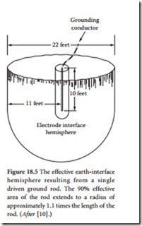
The grounding electrode (or ground rod) interacts with the earth to create a hemisphere-shaped volume, as illustrated in Figure 18.5. The size of this volume is related to the size of the grounding electrode. The length of the electrode has a much greater effect than the diameter. Studies have demonstrated that the earth-to-electrode resistance from a driven ground rod increases exponentially with the distance from that rod. At a given point, the change becomes insignificant. It has
Grounding conductor
been found that for maximum effectiveness of the earth-to- electrode interface, each ground rod requires a hemisphere- shaped volume with a diameter that is approximately 2.2 times the rod length [9].
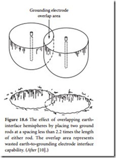
The constraints of economics and available real estate place practical limitations on the installation of a ground sys- tem. It is important, however, to keep the 2.2 rule in mind because it allows the facility design engineer to use the avail- able resources to the best advantage. Figure 18.6 illustrates the effects of locating ground rods too close (less than 2.2 times the rod length). An overlap area is created that effec- tively wastes some of the earth-to-electrode capabilities of the two ground rods. Research has shown, for example, that two 10-ft ground rods driven only 1 ft apart provide about the same resistivity as a single 10-ft rod.
There are three schools of thought with regard to ground-rod length. The first approach states that extending ground-rod length beyond about 10 ft is of little value for most types of soil. The reasoning behind this conclusion is presented in Figure 18.7a, where ground resistance is plotted as a function of ground-rod length. Beyond 10 ft in length, a point of diminishing returns is reached.
The second school of thought concludes that opti- mum earth-to-electrode interface is achieved with long (40 ft or greater) rods, driven to penetrate the local water table. When planning this type of installation, consider the difficulty that may be encountered when attempting to drive long ground rods. The foregoing discussion assumes that the soil around the grounding electrode is reasonably uniform in composition. Depending upon the location, however, this assumption may not hold true.
The third school of thought concludes that the optimum ground-rod installation is achieved by using the longest possible rod depth (length). Data to support this conclusion is given in Figure 18.7b, which plots ground-rod performance as a function of depth in soil
of uniform resistivity. This curve does not take into account seasonal moisture content, changing chemical composition at different soil layers, and frozen soil conditions.
Given these three conflicting approaches, the benefits of hiring an experienced, licensed professional engineer to design the ground system can be readily appreciated.
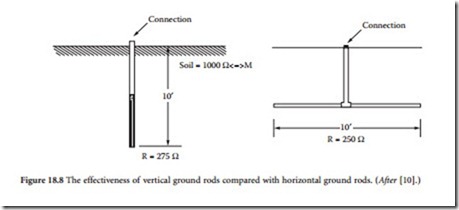
Horizontal grounding electrodes provide essentially the same resistivity as an equivalent-length vertical electrode, given uniform soil conditions. As Figure 18.8 demonstrates, the difference between a 10-ft vertical and a 10-ft horizontal ground rod is negligible (275 vs. 250 Ω). This comparison includes the effects of the vertical connection element from the surface of the ground to the horizontal rod. Taken by itself, the horizontal ground rod provides an earth-interface resistivity of approximately 308 Ω when buried at a depth of 36 in.
Ground rods come in many sizes and lengths. The more popular sizes are 1/2, 5/8, 3/4, and 1 in. The 1/2-in. size is available in steel with stainless-clad, galvanized, or copper-clad rods. All-stainless-steel rods also are available. Ground rods can be purchased in unthreaded or threaded (sectional) lengths. The sec- tional sizes are typically 9/16- or 1/2-in. rolled threads. Couplers are made from the same materials as the rods. Couplers can be used to join 8- or 10-ft-length rods together. A 40-ft ground rod, for example, is driven one 10-ft section at a time.
The type and size of ground rod used is determined by how many sections are to be connected and how hard or rocky the soil is. Copper-clad 5/8-in. × 10-ft rods are probably the most popular. Copper cladding is designed to prevent rust. The copper is not primarily to provide better conductivity. Although the copper certainly provides a better conductor interface to earth, the steel that it covers is also an excel- lent conductor when compared with ground conductivity. The thickness of the cladding is important only insofar as rust protection is concerned.
Wide variations in soil resistivity can be found within a given geographic area, as documented in Table 18.2. The wide range of values shown results from differences in moisture content, mineral content, and temperature.
Temperature is a major concern in shallow grounding systems because it has a significant effect on soil resistivity [11]. During winter months, the ground system resistance can rise to unacceptable levels because of freezing of liquid water in the soil. The same shallow grounding system can also suffer from
high resistance in the summer as moisture is evaporated from soil. It is advisable to determine the natural frost line and moisture profile for an area before attempting design of a ground system.
Figure 18.9 describes a four-point method for in-place measurement of soil resistivity. Four uniformly spaced probes are placed in a linear arrangement and connected to a ground resistance test meter. An alternating current (at a frequency other than 60 Hz) is passed between the two most distant probes, resulting in a potential difference between the center potential probes. The meter display in ohms of resistance can then be applied to determine the average soil resistivity in ohm-centimeters for the hemi- spherical area between the C1 and P2 probes.
Soil resistivity measurements should be repeated at a number of locations to establish a resistivity profile for the site. The depth of measurement can be controlled by varying the spacing between the probes. In no case should the probe length exceed 20% of the spacing between probes.
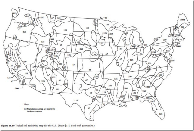
After the soil resistivity for a site is known, calculations can be made to determine the effectiveness of a variety of ground system configurations. Equations for several driven rod and radial cable configurations are given in Reference 11, which — after the solid resistivity is known — can be used for the purpose of estimating total system resistance. Generally, driven rod systems are appropriate where soil resistivity continues to improve with depth or where temperature extremes indicate seasonal frozen or dry soil conditions. Figure 18.10 shows a typical soil resistivity map for the U. S..
Ground Electrode Testing
Testing of all ground electrodes before they are connected to form a complex network is a fairly simple process that is well described in the documentation included with ground electrode meters. This instruc- tional process, therefore, will not be described here. Also, the system as a whole should be tested after all interconnections are made, providing a benchmark for future tests.
At a new site, it is often advisable to perform ground-system tests before the power company ground/ neutral conductor is attached to the system. Conduct a before-and-after test with probes in the same position to determine the influence of the power company attachment [11]. It is also worthwhile to install permanent electrodes and marker monuments at the original probe positions to ensure the repeatability of future tests.
Chemical Ground Rods
A chemically activated ground system is an alternative to the conventional ground rod. The idea behind the chemical ground rod is to increase the earth-to-electrode interface by conditioning the soil surround- ing the rod. Experts have known for many years that the addition of ordinary table salt (NaCl) to soil will reduce the resistivity of the earth-to-ground electrode interface. With the proper soil moisture level (4 to 12%), salting can reduce soil resistivity from perhaps 10,000 Ω/m to less than 100 Ω/m. Salting the area surrounding a ground rod (or group of rods) follows a predictable life-cycle pattern, as illustrated in Fig- ure 18.11. Subsequent salt applications are rarely as effective as the initial salting.
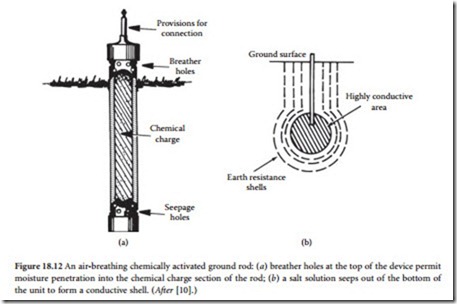
Various approaches have been tried over the years to solve this problem. One such product is shown in Figure 18.12. This chemically activated grounding electrode consists of a 2-1/2-in.-diameter copper pipe filled with rock salt. Breathing holes are provided on the top of the assembly, and seepage holes are located at the bottom. The theory of operation is simple. Moisture is absorbed from the air (when avail- able) and is then absorbed by the salt. This creates a solution that seeps out of the base of the device and conditions the soil in the immediate vicinity of the rod.
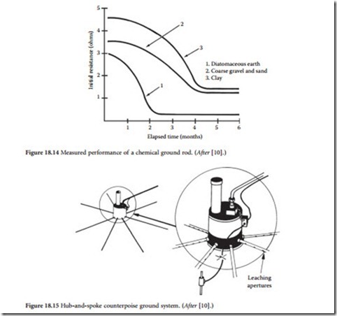
Another approach is shown in Figure 18.13. This device incorporates a number of ports (holes) in the assembly. Moisture from the soil (and rain) is absorbed through the ports. The metallic salts subsequently absorb the moisture, forming a saturated solution that seeps out of the ports and into the earth- to-electrode hemisphere. Tests have shown that if the moisture content is within the required range, earth resistivity can be reduced by as much as 100:1. Figure 18.14 shows the measured performance of a typical chemical ground rod in three types of soil.
Implementations of chemical ground-rod systems vary depending on the application. Figure 18.15 illustrates a counterpoise ground consisting of multiple leaching apertures connected in a spoke fashion to a central hub. The system is serviceable in that additional salt compound can be added to the hub at required intervals to maintain the effectiveness of the ground. Figure 18.16 shows a counterpoise system made up of individual chemical ground rods interconnected with radial wires buried below the surface.
Ufer Ground System
Driving ground rods is not the only method of achieving a good earth-to-electrode interface [9]. The concept of the Ufer ground has gained interest because of its simplicity and effectiveness. The Ufer approach (named for its developer), however, must be designed into a new structure. It cannot be added
on later. The Ufer ground takes advantage of the natural chemical- and water-retention properties of concrete to provide an earth ground. Concrete typically retains moisture for 15 to 30 days after a rain. The material has a ready supply of ions to conduct current because of its moisture-retention properties, mineral content, and inherent pH. The large mass of any concrete foundation provides a good interface to ground.
A Ufer system, in its simplest form, is made by routing a solid-copper wire (no. 4 gauge or larger) within the foundation footing forms before concrete is poured. Figure 18.17 shows one such installation. The length of the conductor run within the concrete is important. Typically a 20-ft run (10 ft in each direction) provides a 5 Ω ground in 1000 Ω/m soil.
As an alternative, steel reinforcement bars (rebar) can be welded together to provide a rigid, conductive structure. A ground lug is provided to tie equipment to the ground system in the foundation. The rebar must be welded, not tied, together. If it is only tied, the resulting poor connections between rods can result in arcing during a current surge. This can lead to deterioration of the concrete in the affected areas.
The design of a Ufer ground is not to be taken lightly. Improper installation can result in a ground system that is subject to problems. The grounding electrodes must be kept a minimum of 3 in. from the bottom and sides of the concrete to avoid the possibility of foundation damage during a large lightning
surge. If an electrode is placed too near the edge of the concrete, a surge could turn the water inside the concrete to steam and break the foundation apart.
The Ufer approach also can be applied to guy-anchor points or a tower base, as illustrated in Figure 18.18. Welded rebar or ground rods sledged in place after the rebar cage is in position can be used. By protruding below the bottom concrete surface, the ground rods add to the overall electrode length to help avoid thermal effects that can crack the concrete. The maximum length necessary to avoid breaking the concrete under a lightning discharge is determined by the following:
• Type of concrete (density, resistivity, and other factors)
• Water content of the concrete
• How much of the buried concrete surface area is in contact with the ground
• Ground resistivity
• Groundwater content
• Size and length of the ground rod
• Size of lightning flash
The last variable is a bit of a gamble. The 50% mean occurrence of lightning strikes is 18 A, but superstrikes can occur that approach 100 to 200 kA.
Before implementing a Ufer ground system, consult a qualified contractor. Because the Ufer ground system will be the primary grounding element for the facility, it must be done correctly.
Bonding Ground-System Elements
A ground system is only as good as the methods used to interconnect the component parts [9]. Do not use soldered-only connections outside the equipment building. Crimped/brazed and exothermic (Cad- welded) connections are preferred. (Cadweld is a registered trademark of Erico Corp.) To make a proper bond, all metal surfaces must be cleaned, any finish removed to bare metal, and surface preparation com- pound applied. Protect all connections from moisture by appropriate means, usually sealing compound and heat-shrink tubing.
It is not uncommon for an untrained installer to use soft solder to connect the elements of a ground system. Such a system is doomed from the start. Soft-soldered connections cannot stand up to the acid and mechanical stress imposed by the soil. The most common method of connecting the components of a ground system is silver soldering. The process requires the use of brazing equipment, which may be unfamiliar to many facility engineers. The process uses a high-temperature/high-conductivity solder to complete the bond- ing process. For most grounding systems, however, the best approach to bonding is the exothermic process.
Exothermic Bonding
Exothermic bonding is the preferred method of connecting the elements of a ground system [9]. Molten cop- per is used to melt connections together, forming a permanent bond. This process is particularly useful in joining dissimilar metals. In fact, if copper and galvanized cable must be joined, exothermic bonding is the only acceptable means. The completed connection will not loosen or corrode and will carry as much current as the cable connected to it. Figure 18.19 illustrates the bonding that results from the exothermic process.
The bond is accomplished by dumping powdered metals (copper oxide and aluminum) from a con- tainer into a graphite crucible and igniting the material by means of a flint lighter. Reduction of the cop- per oxide by the aluminum produces molten copper and aluminum-oxide slag. The molten copper flows over the conductors, bonding them together. The process is illustrated in Figure 18.20. Figure 18.21 shows a typical mold. A variety of special-purpose molds are available to join different-size cables and copper strap. Figure 18.22 shows the bonding process for a copper-strap-to-ground-rod interface.
Ground-System Inductance
Conductors interconnecting sections or components of an earth ground system must be kept as short as possible to be effective [9]. The inductance of a conductor is a major factor in its characteristic impedance to surge energy. For example, consider a no. 6 AWG copper wire 10 m in length. The wire has a dc resistance of 0.013 Ω and an inductance of 10 μH. For a 1000 A lightning surge with a 1 μs rise time, the resistive voltage drop will be 13 V, but the reactive voltage drop will be 10 kV. Furthermore, any bends in the conductor will increase its inductance and further decrease the effectiveness of the wire. Bends in ground conductors should be gradual. A 90° bend is electrically equivalent to a 1/4-turn coil. The sharper the bend, the greater the inductance.
Because of the fast rise time of most lightning discharges and power-line transients, the skin effect plays an important role in ground-conductor selection. When planning a facility ground system, view the project from an RF standpoint.
The effective resistance offered by a conductor to radio frequencies is considerably higher than the ohmic resistance measured with direct currents. This is because of an action known as the skin effect, which causes the currents to be concentrated in certain parts of the conductor and leaves the remainder of the cross section to contribute little or nothing toward carrying the applied current.
When a conductor carries an alternating current, a magnetic field is produced that surrounds the wire. This field continually is expanding and contracting as the ac current wave increases from zero to its maximum positive value and back to zero, then through its negative half-cycle. The changing magnetic lines of force cutting the conductor induce a voltage in the conductor in a direction that tends to retard the normal flow of current in the wire. This effect is more pronounced at the center of the conductor. Thus, current within the conductor tends to flow more easily toward the surface of the wire. The higher the frequency, or the faster the rise time of the applied waveform, the greater the tendency for current to flow at the surface. Figure 18.23 shows the distribution of current in a radial conductor.
When a circuit is operating at high frequencies, the skin effect causes the current to be redistributed over the conductor cross section in such a way as to make most of the current flow where it is encircled by the smallest number of flux lines. This general principle controls the distribution of current regardless of the shape of the conductor involved. With a flat-strip conductor, the current flows primarily along the edges, where it is surrounded by the smallest amount of flux
