Transformer Fundamentals
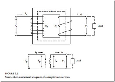
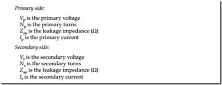
The transformer was invented in 1886 by William Stanley and is a very useful device. A transformer can be divided into three parts: primary wind- ing, secondary winding, and core. The primary and secondary windings are linked by common flux produced in the iron core, as shown in Figure 5.3. The following symbols are used for transformer voltages, currents, and impedances.
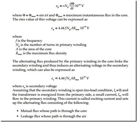
Let us assume that the primary winding is energized by connecting it to an AC supply voltage, Vp. This sets up the primary current, which produces an alternating magnetic field in the iron core that is continually building up and collapsing in both positive and negative directions. The instantaneous induced voltage in the primary winding can be expressed by Faraday’s law as
In commercial power transformers, the leakage flux is very small and is often neglected. The alternating flux in the iron core induces voltage in the primary and secondary windings. The induced voltage in the second- ary produces a back electromotive force (emf) due to self-inductance. According to Lenz’s law, the back emf is equal to applied voltage to the primary winding under no-load conditions. The applied voltage can be expressed as follows:
Applied voltage = total induced voltage – resistance drop in the primary winding
Neglecting the resistance drop in the primary winding, we can write Applied voltage = induced voltage
Vp = ep
When load is applied to the secondary winding, a proportional primary cur- rent will flow corresponding to the secondary current. As the load is applied to the transformer, the voltage transformation ratio will deviate from the true transformer winding turns ratio. These small errors can generally be neglected in power transformers. In addition to the voltage drop in primary and secondary windings, losses due to the exciting current and load current have to be considered. Transformer losses can be divided in two types:
Copper loss (I2R): This is power loss in the resistance of the primary and secondary winding due to load and magnetizing current of transformer.
Core loss: This is power loss in the transformer core and is due to the exciting current. The core loss can be subdivided into eddy current and hysteresis losses. Eddy current losses are due to eddy and small circulating currents in the core, whereas hysteresis losses are caused by the energy required to align the domains in the magnetic core material. Core loss is continuous as long as the transformer is energized.
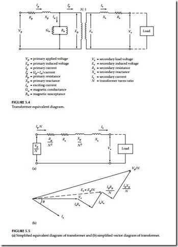
A two-winding power transformer can be represented by an equivalent circuit diagram as shown in Figure 5.4. The exciting current of the transformer, represented by In, is shown as flowing to the magnetizing branch of shunt conductance and susceptance. The exciting current for power transformers usually ranges from 3% to 6%. To simplify the equivalent circuit, the exciting current may be neglected. Furthermore, the equivalent circuit diagram can be based upon the primary or secondary voltage. Figure 5.5a shows the equivalent circuit diagram of a transformer based on the secondary side. Sometimes it is desirable to represent a transformer by vector diagrams (the relationship of the primary and secondary currents and voltages). The vector diagram shown in the Figure 5.5b is based upon the equivalent circuit diagram shown in Figure 5.5a.
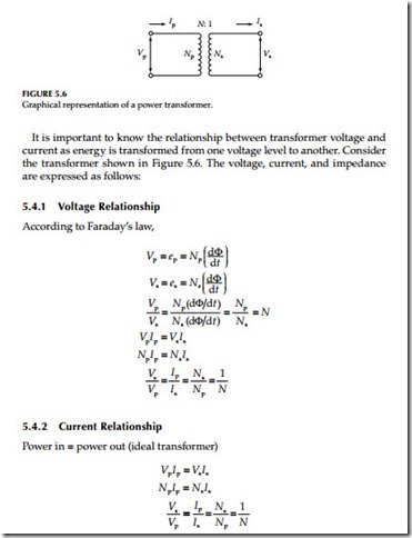
It is important to know the relationship between transformer voltage and current as energy is transformed from one voltage level to another. Consider the transformer shown in Figure 5.6. The voltage, current, and impedance are expressed as follows:
