Controller Used for Frequency Response in Wind Power
Frequency control in power systems is usually formed of primary and secondary control. Future power system will require an active participation of wind power generation on the primary and secondary frequency control. Although generators electronically controller and/or electronically connected to the grid do not provide FR, this capability can be obtained by adding a supplementary control to the power converters.
Several control schemes can be drawn to enable the wind power generation to provide FR, it can be divided into three-level hierarchy [20]:
(i) Wind turbine controller.
(ii) Wind farm controller.
(iii) Power system level controller.
Local control at wind turbine level is used to provide primary frequency control and other additional auxiliary services then wind farm level controller allows coordination between the central and local control in order to achieve the desired generation for the system. Power system level controllers are used for secondary frequency control; it provides better system frequency behavior by the coordination between the AGC and the wind farms.
Wind Turbine Level Controllers
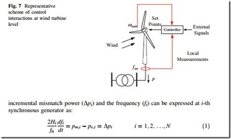
Wind turbine level controllers are local controllers added to the VSWT subsystems in order to enable transiently support the frequency (see Fig. 7). They can enable the primary frequency control by two strategies: inertial controller and governor controller.
Inertia Controller
Under system frequency disturbance conditions (active power imbalance between generation and demand), the generator-demand dynamic relationship between the
pm,i is the mechanical power of prime mover in p.u., pe,i is the electrical power in p.u., Dpi is the load generation imbalance in p.u., Hi is the inertia constant in seconds of i-th generator, Hi is given in seconds and is a measure of the time that a rotating generator can provide rated power without any input power from the turbine.
fi is the frequency in Hz, f0 is its rated value, and dfi/dt is the frequency change in Hz/s.
This is a simplified version of the swing equation, considering damping effect to be small during the event. Now, it is simple to understand frequency behavior of a traditional power system during a system frequency disturbance using (1). If demand is greater than generation (pe,i [ pmi, Dpi \ 0), the frequency falls (dfi/ dt \ 0) while if generation is greater than demand, the frequency rises (dfi/dt [ 0).
The same reasoning that is used in mechanics to introduce the concept of center of mass can be invoked for the definition of a frequency of inertia center (COI). This frequency is denoted by fCOI and corresponds to the inertia-weighted average of all generator frequencies:
where HT is the total inertia of the system.
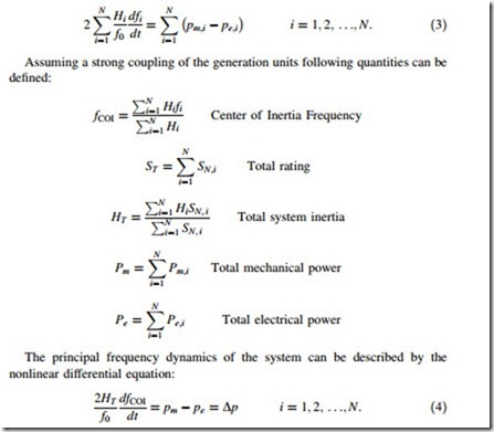
In a highly meshed power system, all units can be assumed to be connected to the same bus, representing the COI of the system and assuming further simplifications, they can even be condensed into one single equivalent unit. A summation of all Eq. (1) for the N generators in the system yields:
During a system frequency disturbance the system frequency will change at a rate initially determinate by the total system inertia (HT).
The contribution of the total system inertia of one load or generator (Hi) depend if the system frequency causes change in its rotational speed and, then, its kinetic energy.
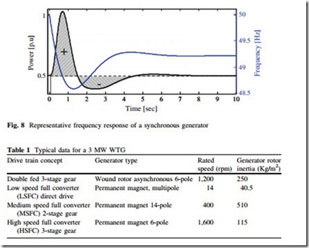
The power associated with this change in kinetic energy is fed or taken from the power system and is known as the inertial response. It must be noticed inertial response is dominated during the initial frequency change, at the very beginning this is dominant dynamic process, however, after a very short time period where the kinetic energy is released governor control start to made a dominant presence in the FR. Figure 8 shows a representative FR provided by a synchronous
Permanent magnet, multipole 14 40.5
Permanent magnet 14-pole 400 510
Permanent magnet 6-pole 1,600 115
generator and change in the energy is depicted on the shadow area below the active power response.
The objective of the inertia control is to enable temporarily increase power output during frequency disturbance. This control requires some sort of energy storage to be able to increase the power production. The concept is therefore easily applicable to WTG, which have a reasonably large amount of kinetic energy stored in the rotating parts. The inertia control allows the converter and other subsystem in the WTG to extract the stored inertial energy from the moving part on WTGs: blades, gearbox, generator, etc. Table 1 shows typical values of generator rotor inertia for 3 MW modern variable speed WTG.
Considering per unit values, the inertia constant of a wind turbine generator is in the order of 2.0–6.0 s, which is comparable to traditional synchronous generation with various types of turbines and a resulting inertia constant in the range of 2.0–10.0 s. It explains why this controller is typically designed for an energy contribution of a very short duration (i.e., first 10.0 s of frequency disturbance).
The inertia controller can be created in several ways, there are two basic approaches:
(i) Releasing ‘‘Hidden Inertia’’
(ii) Fast Power Reserve Emulation.
Releasing ‘‘Hidden Inertia’’
A VSWT can emulate FR similar to the inertial response provided by synchronous generator by implementing an inertial controller. This controller is a simple control loop added on the power converter controller, it creates an active power control signal (inertial power PHsyn) following a version of the swing Eq. (4) [18, 21, 22]:
where Hsys express the synthetic or emulated inertia (sec) and fsys system frequency in per unit. Implementation of releasing hidden inertia controllers is depicted in Fig. 9.
The WTG can quickly store and release a large amount of kinetic energy in the rotating masses because of the power electronic converter, due to a large amount of inertia and wide rotational speed. The inertia controller helps to reduce the maximum frequency change rate and increases the transient frequency nadir. Comparison with FSWT and conventional generators, the inertia controller releases considerably larger kinetic energy.
Fast Power Reserve Emulation
The fast-power reserve emulation controller is designed to provide a short term constant power, and it can provide FR for a short period of time [23–25]. The fast- power reserve (PHsyn) is derived from a simple integration of kinetic energy stored in the wind turbine rotor:
where t (t \ tmax) is the lasting time of the fast-power reserve since the beginning of the frequency disturbance, xr, 0 is the initial rotational speed and xr, f is the rotor rotational speed corresponding to t.
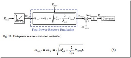
This controller acts on the reference rotational speed creating an artificial change on the rotational speed to allow release kinetic energy from the wind turbine rotor. The change on the rotational speed (xr, ref) is obtained as:
A general scheme for the fast-power reserve emulation controller is depicted on Fig. 10.
The fast power reserves provides FR for a short period and save time for other slower generators to participate in the frequency control.
Governor Response Controller
The objective of the primary control is to maintain the balance between generation and load. It corresponds to a proportional controller (P-controller) based on the classical control theory. The governor provides the control between frequency and generation power in a generator participating in primary frequency control. The governor of a generator provides the governor response and it is expected to be available within a few seconds (depending on intrinsic time contestants) after system frequency disturbance.
The governor control refers to control actions that are done locally (on the power plant level) based on the set-points for frequency and power. The actual values of these can be measured locally, and deviations from the set values results in a signal that will influence the valves, gates, servos, etc. in a primary-controlled power plant, such that the desired active power output is delivered. In primary frequency control, the control task of priority is to bring the frequency back to (short term) acceptable values. However, there remains an unavoidable frequency control error because the control law is purely proportional. Also, this controller cannot have an integral component because the integrators of different power plants could start ‘‘competing’’ each other for power production shares, which can lead to an unpredictable and unreasonable distribution of power generation on the available plants.
The control task is shared by all generators participating in the primary frequency control irrespective of the location of the disturbance.
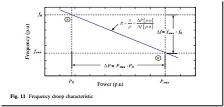
The steady-state properties of the governor controller is defined by the permanent droop (q), which define is defined as the change in frequency (Df), normalized to the nominal frequency (f0), divided by the change in power output (DP), normalized to a given power base, (Pbase).
The droop controller is described by a steady-state frequency characteristic as shown on Fig. 11. It produces an active power change that is proportional to the frequency deviation.
Frequency droop control can be included as a control loop in modern wind turbines based on generators electronically controller and/or electronically con- nected to the power system. Figure 12 shows an implementation of the frequency droop control for a converter-based VSWT [22, 26, 27].
The droop control in WTG emulates the similar frequency droop characteristic to the synchronous generators. However, the power increase (DP) during a sudden drop on system frequency must be obtained from the kinetic energy of the rotation parts of WTG, it causes a decrease on rotational speed due to the Maximum Power Point Tracking (MPPT) operation. The support of steady-state frequency requires extra steady-state power to reduce the frequency deviation; this extra-power is provided in long term from the prime-mover in classical generation units.
Droop controller has not high impact on the initial ROCOF after frequency disturbance but largely influences the frequency nadir. However, decrease on rotational speed on wind turbines equipped with droop controllers may not be
avoided because extra wind speed cannot be obtained, for this reason droop controller require support of other wind turbine components to avoid turbine stall by rotational speed falling too low. This issue can be solved using two approaches:
(i) Stopping Frequency Droop Contribution.
(ii) De-loading the wind turbine.
Frequency droop controller can be equipped with a triggering system to allow finish the action control on time to avoid a potential stall condition on the wind turbine. This triggering off system is similar to one use in fast power reserve emulation. This solution is easily implemented; however, its real benefit is on doubt because power contribution will be interrupted creating a potential risk of frequency disturbance.
Another solution is to use the droop controller combined with a de-loading control. De-loading the wind turbine is a technique that enables it to operate a lower operation point (speed-power) instead of the optimal provided by the MPPT controller. This operation condition saves the available power in the wind as reserves. This controller is described in the next section.
4.2.1 De-loading Control
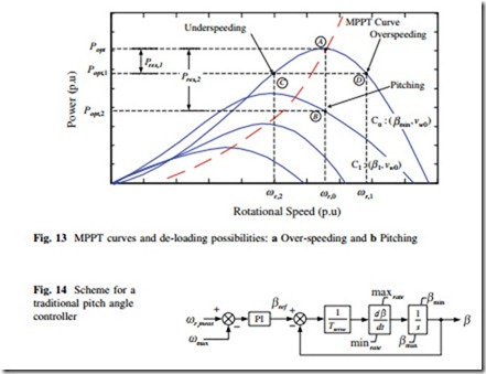
When the wind speed is below the rated value (vw \ vw,0), traditional VSWT, always operate on the MPPT condition with the constant blade pitch angle (b = bmin). This operation mode allows extracting power from the wind energy as much as possible. The maximum power-tracking curve is shown in Fig. 13. The MPPT curve is given is used to define the power reference at any rotor speed for the active power control of VSWT.
Usually, the pitch angle of the wind turbine is equal to zero during the MPPT operation condition while the wind speed is below the rated value. If the wind speed increases and exceeds the rated value, the pitch angle starts to increase to keep the active power output on its rated value [28, 29].
The operation of WTG at MPPT condition allows the active power output has reached the maximum value at the instant wind speed. However, there are no power reserves from the wind turbine, and using the kinetic energy from the rotor mass of the wind turbine can only give a short-term frequency droop control.
The de-loading control can enable wind turbines to save some active power as reserves. The active power production in a VSWT can be controlled acting on pitch angle (b) and rotational speed (x), as consequence, the de-loading operation can be realized by two ways: (i) pitch control (pitching action) and (ii) over- speeding control.
a. Pitching Control.
Assuming a constant wind speed (vw0) and constant rotational speed (xr,0) the active power of a VSWT can be reduced from the MPP (point A, Fig. 13) by regulating the pith angle bmin to a large value b1 (point B), this new operative condition allows a power reserve (Pres, 2 = Popt-Popt, 2). This action is known as pitching and a modification on the pith angle controller is required to modify the pitch angle-rotational speed characteristic (move from curve C0 to C1 on Fig. 13).
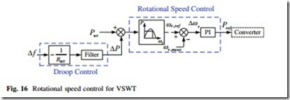
A representative scheme of a traditional pitch angle controller is shown on Fig. 14, it acts when the rotational speed is above the maximum value for a high wind speed condition.
Traditional pitch angle controller must be modified to allow pitching, one approach includes a proportional integral control for pitch angle control, it avoids the use of a mechanical characteristics look-up table, usually needed to identify the required pitch angle and reference speed that would lead to the required response [30]; this implementation is depicted in Fig. 15.
One important aspect of the pitching approach is that response of pitch angle controller is slow because the mechanical time constant of pitch angle controller.
The pitching approach provides sufficient reserves for systems and save investment of the reserves and storages; however, this control strategy requires a careful market evaluation, or it can be adopted only a few hours per year. The de- loading operation of wind turbines without any financial incentive to provide this power reserves service produce loss of annual revenues for wind park developers will be reduced. This approach is always preferable to the disconnection of wind generators in specific operational conditions because of the lack of operational security in the system.
This control strategy should be performed through a hierarchical control approach, it allows the coordination of the activation of the adoption of de-load margins, definition of droop settings, and other control parameters of the WTG. A hierarchical control approach allows to transmission system operator (TSO) to send requests, to be transformed in control settings by the wind generation dis- patch centers, that finally will interact with the wind parks and wind turbines in the field.
The de-loading approach involves a set of other problems, like the identification of the needed volume of de-load margins for a given set of operating conditions in a system, which requires further research.
b. Rotational Speed Control.
Assuming a constant wind speed (vw0) and constant pitch angle (bmin) the active power of a VSWT can be reduced from the MPP (point A, Fig. 13) by increasing the rotational speed over the MPPT speed (xr,1 [ xr,0, point D), this action is known as over-speeding. This is a more convenient operation than pitching action when the rotational speed is below the maximum value, and it can protect the pitch blade of wear and tear compared for low wind speeds.
Decreasing the rotational speed below the MPPT speed (under-speeding) is one more de-loading alternative. However, this alternate forces the WTG operation at lower rotational increasing risk of stalling. On the other hand, over-speeding operation allows more kinetic energy stored in the blade as consequence if the WTG is equipped with inertia controller the FR is improved.
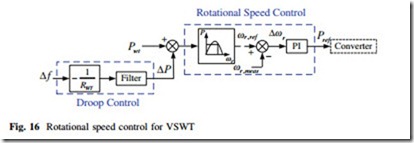
Figure 16 shows a general scheme for a rotational speed controller for a VSWT. The over-speeding operation of VSWT has the advantages to provide sufficient reserves for systems and save investment of the reserves and storages although the wind energy may be partially lost if changes on speed produce stall. The wind power regulation is faster than the thermal power regulation due to the PWM control technology and the power system will be more stable than MPPT condition.
Wind Farm Level Controller
The effective frequency support from WTG requires a coordination of all individual frequency controllers installed inside the wind farm, as a consequence a hierarchical structure of control is used. Two major control system are defined at wind farm level:
(i) Central control and
(ii) Local control.
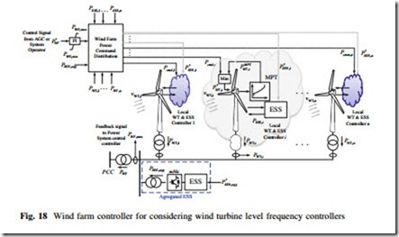
The main objective of the central control is to control active power of the whole wind farm (PWF) by sending out set points to all wind turbines. Local control ensures the set-points at wind turbine level are reached and sends back information about of generation capabilities to the central controller.
The massive use of energy storage systems (EES) is expected on the future power systems for several reasons; one of them is to support the massive inte- gration of wind power. Two ESS configurations can be used for wind farms:
(i) Large agregated EES.
(ii) Small distributed ESS.
There are several technical and economic differences between technologies EES used by each configuration. Large aggregated EES often are directly con- nected to the power system based on the external and nonwind technologies like batteries, compressed air, and pumped hydro for the whole wind farm. Small distributed ESS is a local solution located on terminal of the wind turbine or inside it (typically connected across DC link). Batteries [31], super-capacitors [32], and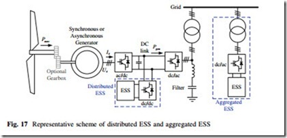
flywheels [33, 34] are the main technologies used as small distributed ESS in wind farms. The choice of ESS depends on the demands of the control process. From the point of view of reaction time, distributed ESS is typically faster than large aggregated ESS energy storage devices. Fast- and medium-term ESS are suitable tor frequency control [35]. A generic scheme of small-distributed ESS on VSWT is shown on Fig. 17.
The central controller receives an active power control signal from the system operator (P*) and produce two sets of individual signals: (a) Power command signals for wind turbine controller (Pcmd; i) in order to de-load wind turbine based on local data (MPPT, vw, etc.), (b) Power command signals to distributed ESS controller Feedback signals from each individual wind turbine are taken to the central controller to provide an online monitoring and control system. Also, the central controller acts on the aggregated ESS to ensure an overall control (see Fig. 18).
The active power set point of the wind farm (P*) must be appropriately allocated to each wind turbine and ESS units by the wind farm central control, following a power balance:
where PWT; total is the total active power command for the wind turbines and PESS; total is the total active power command by the ESS. The internal power losses in the wind farm (PWF; losses) are assumed negligible for simplicity.
An important aspect is the distribution scheme of individual active power
open for research because there are several aspects to be included. The distribution scheme must consider several important aspects affecting the power production inside the wind farm wake effect, random wind speed, etc.
Incentive mechanism must be defined to encourage wind farm proprietary to provides frequency support services, de-loading wind turbines is an technical
aspect with financial impact, however, not all wind turbines in the wind farm are necessary to operate at de-loading mode. In fact, migration to more on-line market controls can allow central control of wind farm an optimal decision of how many wind turbines inside a wind farm should be de-loaded in order to cope with a security risk and responding to economic signals provided by the market.
ESS capability and economic benefits should be carefully investigated. Modern ESS has limited frequency support due to the little capacity of batteries, super- capacitor, flywheel, etc., and very low time response of hydro-pump, CAES, etc. ESS may reduce the system frequency excursion for a relatively short period of time, however, ESS cannot influence the steady-state frequency. Therefore, con- ventional power plants and wind power must be rectified to support long-term frequency control. Consideration about security and risk must be carefully examined during the recharge period of ESS to avoid a frequency stability event.
Power System Level Controller
Frequency support from wind power at wind turbine level and wind farm level are aspects well documented. However, there are few studies focus on the power system level frequency control considering wind power penetration. Massive penetration of wind power is expected in future power systems, as consequence frequency control must be provided.
The main controllers used for primary frequency control in wind turbines and wind farm are presented in the previous sections and the tertiary control is not taken into account.
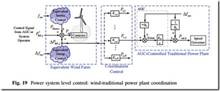
The power system level controller is a slow global controller related to quasi- steady state processes (*30 min) of secondary frequency control. The objective of this controller is to restore the frequency to rated frequency, it is reached by adjusting the set-point of power generation at power plant with capability of modify its power dispatch. This section presents a description of a power system level controller based on the coordination between wind power generation and traditional generation. This pseudo-AGC controls the traditional power plants to be aware of the frequency control support provided by the wind farms as soon as possible. A wind farm including inertial and droop controllers are enough to provided system frequency support and improve the frequency stability but an coordinated power system control can provided an even better frequency behavior. Figure 19 shows a power system level control; equivalent model of the i-th wind farm participating on frequency control is depicted.
A coordination control is used as interface between the wind farms with participation on frequency support an traditional power plants. During a frequency disturbance, the inertial response provided by the wind farm with inertial controller helps to modify the maximum frequency change rate and nadir, it has been discussed in previous sections. These indicators of quality in system frequency may be improved in future power system by the coordination between wind farm with FR capability and AGC-controlled traditional power plants. The droop power (DPWF, i) provided but the i-th wind farm participating in frequency support is divided by the coordination control following the rule as follows:
where Pc,j is the coordination control signal, Kc,j is the participation factor for each traditional power plant supporting the wind farm. In a highly competitive environment, as expected in future power system, this participation factor is a time- dependent variable and must be calculated dynamically.
The coordination signals (Pc, j) modify the AGC error which is similar to the area control error (ACE) and the traditional power plants receive an appropriate signal of the power imbalance since the very beginning. This coordinated control provides an early frequency support from the traditional power plants and the system frequency can be controlled and recovered back to the nominal frequency faster than the no coordinated control condition. The coordinated control presented is based on the same principle as the tie bias control, but the AGC error uses the coordination control signal (Pc, j) instead of the lie line power deviation.
