Crankshaft bearings
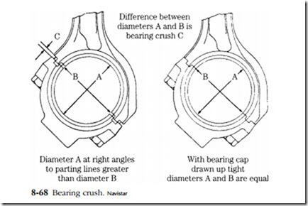
All modern engines are fitted with two-piece precision insert bearings at the crankpin, as illustrated in Figs. 8-50 and 8-51. Most employ similar two-piece inserts, or shells, at the main journals, although full-circle bearings are appropriate for barrel- type crankcases. No bearing can be allowed to spin in its carrier.1 Full-circle bearings pressed into their carriers or locked by pins or cap screws. Two-piece shells secure with a tab and gain additional resistance to spinning from residual tension. Bearing shells are slightly oversized, so that dimension A in Fig. 8-68 is greater than dimension B. The difference is known as the crush height. Torquing the cap equalizes the diameters, forcing the inserts hard against their bosses.
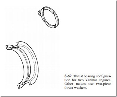
Thrust bearings, usually in the form of flanges of main inserts, limit crankshaft fore-and-aft movement (Fig. 8-69). So long as the crankpin is not tapered, connecting- rod thrust loads are insignificant and transfer through rubbing contact between the rod big end and the crankpin flanges.
Insert-type bearings are made up in layer-cake fashion of a steel backing and as many as five tiers of lining material. Although their numbers are dwindling, perhaps half of the high-speed engines sold in this country continue to use copper-lead bear- ings, the best known of which is the Clevite (now Michigan)-77. The facing surface of this bearing consists of 75% copper, 24% lead, and a 1% tin overplate. Daimler- Benz, Perkins, and several other manufacturers have followed the example of Caterpillar and specify aluminum-based bearings, which tolerate acidic oils better
Normal bearing wear should not exceed 0.0005 in. per 1000 hours of continuous operation. The operative word is “continuous”—frequent startups, cold loads, and chronic overloads can subtract hundreds of hours from the expected life. In practice, main bearings outlast crankpin bearings by about three to one, although No. 1 main, which receives side loads from accessories, can fail early.
According to Michigan Bearing, 43% of failings can be attributed to dirt, 15% to oil starvation, 13% to assembly error, and 10% to misalignment. Overloading, corrosion, and miscellaneous causes account for the remainder. In other words, the mechanic con- tributes to most failures, by either assembling dirt into the engine, reversing nonsym- metrical bearing shells or bearing caps, or failing to provide adequate lubrication during initial start-up. These matters are discussed in the next section.
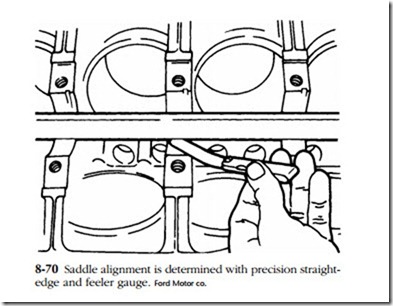
Bearing alignment problems come about from improperly seated rod caps or from warped main-bearing saddles. The condition can sometimes be spotted during disassembly as accelerated wear on outboard or center mainbearing shells. The mechanic should verify alignment by spanning the saddles with a precision straight- edge (Fig. 8-70). Loss of contact translates as block warp.
Bearing alignment can be restored, but at the cost of raising the crankshaft cen- terline a few thousandths of an inch. The effect of chain-driven camshafts is to retard valve timing by an almost imperceptible amount; but gear trains are not so forgiving and the machinist might be forced to resort to some fairly exotic (and expensive) techniques to maintain proper tooth contact. The “cleanest” solution is to resize the bearing bosses by a combination of metalizing and honing.


