Main classes of cable
Cables for the electricity supply industry
MV paper-insulated cables
Until the late 1970s, the large quantities of paper-insulated lead covered (PILC) cables used in the UK electricity supply industry for MV distribution circuits were manufactured according to BS 6480. These cables also incorporated steel wire armour (SWA) and bitumenized textile beddings or servings. An example is illustrated in Fig. 9.1. The lead sheath provided an impermeable barrier to moisture and a return path for earth fault currents and the layer of SWA gave mechanical protection and an improved earth fault capacity. PILC cable continues to be specified by a few utilities; although conversion to XLPE designs are planned.
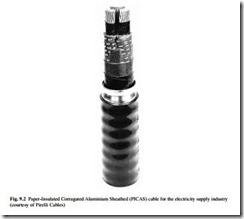
Following successful trials and extensive installation in the early 1970s, a new standard (ESI 09-12) was issued in 1979 for Paper-Insulated Corrugated Aluminium Sheathed (PICAS) cable. This enabled the electricity supply industry to replace expensive lead sheath and SWA with a corrugated aluminium sheath which offered a high degree of mechanical protection and earth fault capability, while retaining the proven reliability of paper insulation. The standard was limited to three conductor cross sections
(95 mm2, 185 mm2 and 300 mm2) using stranded aluminium conductors with belted paper insulation; although it later included designs with screened paper insulation. An example of PICAS cable is shown in Fig. 9.2. A PICAS cable was easier and lighter to install than its predecessor and it found almost universal acceptance in the UK electricity supply sector. It is still being specified by a few utilities, but as with PILC, a switch to XLPE designs is planned.
MV polymeric cables
High-quality XLPE cable has been manufactured for over 25 years. IEC 502 (revised in 1998 as IEC 60502) covered this type of cable and was first issued in 1975. A com- parable UK standard BS 6622 was issued in 1986 and revised in 1999.
The following features are now available in MV XLPE cables and these are accepted by the majority of users in the electrical utility sector:
● copper or aluminium conductors
● semiconducting conductor screen and core screen (which may be fully bonded or easily strippable)
● individual copper tape or copper wire screens
● PVC, LSF or MDPE bedding
● copper wire collective screens
● steel wire or aluminium armour
● PVC, LSF or MDPE oversheaths
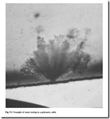
Early experience in North America in the 1960s resulted in a large number of premature failures, mainly because of poor cable construction and insufficient care in avoiding contamination of the insulation. The failures were due to water treeing, which is illustrated in Fig. 9.3. In the presence of water, ionic contaminants and oxidation products, electric stress gives rise to the formation of tree-like channels in the XLPE insulation. These channels start either from defects in the bulk insulation (forming bow-tie trees) or at the interfaces between the semiconducting screens and the insulation (causing vented trees). Both forms of trees cause a reduction in electrical strength of the insulation and can eventually lead to breakdown. Water treeing has
largely been overcome by better materials in the semiconducting screen and by improvements in the quality of the insulating materials and manufacturing techniques, and reliable service performance has now been established.
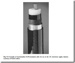
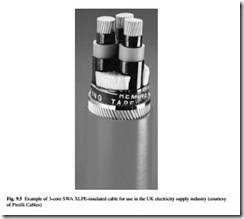
The UK electricity supply industry gradually began to adopt XLPE-insulated or EPR-insulated cable for MV distribution circuits from the early 1990s in place of the PILC or PICAS cables. Each distribution company has specified the best construction for its particular needs. An example of the variation between companies is the difference in practice between solidly bonded systems and the use of earthing resistors to limit the earth fault currents. In the former case, the requirement might typically be to withstand an earth fault current of 13 kA for three seconds. In the latter case, only 1 kA for one second might be specified and the use of single-core cable with a copper wire screen in place of a 3-core cable with a collective copper wire screen or SWA is viable. Different cross-sectional areas of copper wire screen may be specified depending on the earth fault level in the intended installation network. The majority of specific designs being used by the UK electricity supply industry are now incorporated into BS 7870-4.10 (for single core) or BS 7870-4.20 (for 3-core). Examples of XLPE cable designs being used or considered by the UK distribution companies are shown in Figs 9.4, 9.5 and 9.6. The latter shows the most commonly adopted design for 11 kV networks, with a similar design used for 33 kV networks although with stranded copper conductors due to the higher load transfer requirements. The MDPE sheaths are specified for buried installations, with LSF used for tunnel applications.
LV polymeric cables
Protective Multiple Earthed (PME) systems which use Combined Neutral and Earth (CNE) cables have become the preferred choice in the UK public supply network, both for new installations and for extensions to existing circuits. This is primarily because of the elimination of one conductor by the use of a common concentric neutral and earth, together with the introduction of new designs which use aluminium for all phase conductors.
Before CNE types became established, 4-core paper-insulated sheathed and armoured cable was commonly used. The four conductors were the three phases and neutral, and the lead sheath provided the path to the substation earth. The incentive for PME was the need to retain good earthing for the protection of consumers. With the paper cables, while the lead sheath itself could adequately carry prospective earth fault currents back to the supply transformer, the integrity of the circuit was often jeopardised by poor and vulnerable connections in joints and at terminations. By using the neutral conductor of the supply cable for this purpose the need for a separate earth conductor was avoided.
The adoption of 0.6/1 kV cables with extruded insulation for underground public supply in the UK awaited the development of cross-linked insulation systems with a performance similar to paper-insulated systems in overload conditions. An example of the
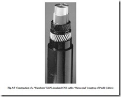
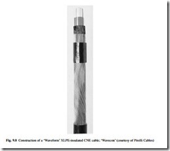
cables which have been developed is the Waveform CNE type which is XLPE-insulated and has the neutral/earth conductor applied concentrically in a sinusoidal form. Insulated solid aluminium phase conductors are laid up to form a three-phase cable and the CNE conductor consists of a concentric layer of either aluminium or copper wires.
If the wires in the CNE conductor are of aluminium, they are sandwiched between layers of unvulcanized synthetic rubber compound to give maximum protection against corrosion. This construction is known as Waveconal and is illustrated in Fig. 9.7. Where the CNE conductors are of copper, they are partially embedded in the rubber compound without a rubber layer over the wires. This is termed Wavecon and is illustrated in Fig. 9.8. Some electricity companies initially adopted Wavecon types because of concern over excessive corrosion in the aluminium CNE conductor, but through standardization all companies had moved to the use of copper wire design by 2001. Waveform cables are manufactured in accordance with BS 7870-3.4.
Both waveform types are compact, with cost benefits. The aluminium conductors and synthetic insulation result in a cable that is light and easy to handle. In addition, the waveform lay of the CNE conductors enables service joints to be readily made without cutting the neutral wires, as they can be formed into a bunch on each side of the phase conductors.
Industrial cables
‘Industrial cables’ are defined as those power circuit cables which are installed on the customer side of the electricity supply point, but which do not fall into the category of ‘wiring cables’.
Generally these cables are rated 0.6/1 kV or above. They are robust in construction and are available in a wide range of sizes. They can be used for distribution of power around a large industrial site or for final radial feeders to individual items of plant. Feeder cables might be fixed or in cases, such as coal-face cutting machines and mobile cranes they may be flexible trailing or reeling cables.
Many industrial cables are supplied to customers’ individual specifications and since these are not of general interest they are not described here. The following sections focus on types which are manufactured to national standards and which are supplied through cable distributors and wholesalers for general use.
Paper-insulated cables
For ratings between 0.6/1 kV and 19/33 kV, paper-insulated cables for fixed installations were supplied in the UK to BS 480, and then to BS 6480 following metrication in 1969. These cables comprise copper or aluminium phase conductors insulated with lapped paper tapes, impregnated with MIND compound and sheathed with lead or lead alloy. For mechanical protection they were finished with an armouring of steel tapes or steel wire and a covering of bitumenized hessian tapes or an extruded PVC oversheath.
The 3-core cables of this type with SWA have been preferred for most applications and these have become known as Paper-Insulated Lead-Covered Steel Wire Armoured (PILCSWA) cables. Single-core cables to BS 6480 do not have armouring; this is partly because the special installation conditions leading to the selection of single-core do not demand such protection and partly because a non-magnetic armouring, such as aluminium would be needed to avoid eddy current losses in the armour. These single- core cables are known as Paper-Insulated Lead Covered (PILC).
It has already been observed that paper-insulated cables are now seldom specified for industrial use, but BS 6480 remains an active standard.
Polymeric cables for fixed installations
The XLPE-insulated cables manufactured to BS 5467 are generally specified for 230/400 V and 1.9/3.3 kV LV industrial distribution circuits. These cables have superseded the equivalent PVC-insulated cables to BS 6346 because of their higher current rating, higher short-circuit rating and better availability.
For MV applications in the range 3.8/6.6 kV to 19/33 kV, XLPE-insulated wire- armoured cables to BS 6622 are usually specified.
Multi-core LV and MV cables are normally steel wire armoured. This armouring not only provides protection against impact damage for these generally bulky and exposed cables, but it is also capable of carrying very large earth fault currents and provides a very effective earth connection.
Single-core cables are generally unarmoured, although aluminium wire armoured versions are available. Single-core cables are usually installed where high currents are present (for instance in power stations) and where special precautions will be taken to avoid impact damage. For LV circuits of this type, the most economic approach is to use unarmoured cable with a separate earth conductor, rather than to connect in parallel the aluminium wire armour of several single-core cables. For MV applications, each unarmoured cable has a screen of copper wires which would together provide an effective earth connection.
Even in the harsh environment of coal mines, XLPE-insulated types are now offered as an alternative to the traditional PVC- and EPR-insulated cables used at LV and MV, respectively. In this application the cables are always multi-core types having a single or double layer of SWA. The armour has to have a specified minimum conductance because of the special safety requirements associated with earth faults and this demands the substitution of some steel wires by copper wires for certain cable sizes.
Where LSF fire performance is needed, LV wire-armoured cables to BS 6724 are the established choice. These cables are identical in construction and properties to those made to BS 5467 except for the LSF grade of sheathing material and the associated fire performance. Cables meeting all the requirements of BS 6724 and, in addition, having a measure of fire resistance such that they continue to function in a fire are standardized in BS 7846, further details of which are given in section 9.3.3. Similarly, BS 7835 for MV wire-armoured cable, which is identical to BS 6622 apart from the LSF sheath and fire performance, was issued in 1996 and revised in 2000.
The only other type of standardized cable used for fixed industrial circuits is multi-core control cable, often referred to as auxiliary cable. Such cable is used to control industrial plant, including equipment in power stations. It is generally wire- armoured and rated 0.6/1 kV. Cables of this type are available with between 5 and 48 cores. The constructions are similar to 0.6/1 kV power cables and they are manu- factured and supplied to the same standards (BS 5467, BS 6346 and BS 6724, as appropriate).
Polymeric cables for flexible connections
Flexible connections for both multi-core power cables and multi-core control cables are often required in industrial locations. The flexing duty varies substantially from application to application. At one extreme a cable may need to be only flexible enough to allow the connected equipment to be moved occasionally for maintenance. At the other extreme the cable may be needed to supply a mobile crane from a cable reel or a coal-face cutter from cable-handling gear.
Elastomeric-insulated and sheathed cable is used for all such applications. This may have flexible stranded conductors (known as ‘class 5’) or highly flexible stranded conductors (known as ‘class 6’). Where metallic protection or screening is needed, this comprises a braid of fine steel or copper wires. For many flexible applications the cable is required to have a resistance to various chemicals and oils.
Although flexible cables will normally be operated on a 230/400 V supply, it is normal to use 450/750 V rated cables for maximum safety and integrity.
A number of cable types have been standardized in order to meet the range of performance requirements and the specification for these is incorporated into BS 6500. Guidance on the use of the cables is provided in this standard and further information is available in BS 7540.
Wiring cables
The standard cable used in domestic and commercial wiring in the UK since the 1960s is a flat PVC twin-and-earth type, alternatively known as 6242Y cable. This comprises a flat formation of PVC-insulated live and neutral cores separated by a bare earth conductor, the whole assembly being PVC-sheathed to produce a flat cable rated at 300/500 V. Cable is also available with three insulated cores and a bare earth, for use on double-switched lighting circuits. These forms of cable are ideal for installation under cladding in standard-depth plaster. They are defined in BS 6004, which covers a large size range, only the smaller sizes of which are used in domestic and commercial circuits.
There are other cable types included in BS 6004 which have more relevance to non- domestic installations. These include cables in both flat and circular form, similar to the 6242Y type but with an insulated earth conductor. Circular cables designated 6183Y are widely used in commercial or light industrial areas, especially where many circuits are mounted together on cable trays. Also included in BS 6004 are insulated conductors designated 6491X which are pulled into conduit or trunking in circuits where mechanical protection or the facility to re-wire are the key factors.
Of recent years, LSF versions of the twin-and-earth cables and the conduit wires have become available and are being used in installations where particular emphasis on fire performance is required. Such cables are included in BS 7211. These are commonly known as 6242B (for twin flat) or 6491B (for single-core conduit wire).
A significant change occurred in 2004 for all fixed wiring in electrical installations in the UK. An amendment was published to BS 7671 (the IEE Wiring Regulations) which specified new cable core colours to bring the UK more closely into line with practice in mainland Europe; the term harmonized core colours is often used. For single-phase fixed installations, the red phase and black neutral are replaced by brown phase and blue neutral, as used for many years in flexible cables for appliances. For three phase cables, the new phase colours are brown, black and grey instead of red, yellow and blue, with the neutral now blue instead of black. In both cases, the protective conductor is still identified by a green–yellow combination. An alternative for three-phase cables is for all phase cores to be brown and marking of L1, L2 and L3 to be carried out at terminations. The neutral will be blue again in this case. Electrical installations commenced after 31 March 2004 may use either the new harmonized core colours or the pre-existing colours, but not both. New installations after 31 March 2006 must only use the harmonized core colours.
An alternative type of cable with outstanding impact and crush strength is mineral- insulated cable (MICC) manufactured to BS EN 60702-1. This is often known by its trade name, Pyrotenax. In a MICC cable, the copper line and neutral conductors are positioned inside a copper sheath, the spaces between the copper components being filled with heavily compacted mineral powder of insulating grade. Pressure or impact applied to the cable merely compresses the powder in such a way that the insulation integrity is maintained. The copper sheath often acts as the circuit earth conductor. An oversheath is not necessary but is often provided for reasons of appearance or for external marking. An MICC cable has a relatively small cross section and is easy to install.
In shopping and office complexes or in blocks of flats there may be a need for a distribution sub-main to feed individual supply points or meters. If this sub-main is to be installed and operated by the owner of the premises, then a 0.6/1 kV split-concentric service cable to BS 4553 may be used. This comprises a phase conductor insulated in PVC or XLPE, around which is a layer of copper wires and an oversheath. Some of the copper wires are bare and these are used as the earth conductor. The remainder are polymer-covered and they make up the neutral conductor. For larger installations, 3-core versions of this cable are available to manufacturers’ specification.
In circuits supplying equipment for fire detection and alarm, emergency lighting and emergency supplies, regulations dictate that the cables will continue to operate during a fire. This continued operation could be ensured by measures, such as embed- ding the cable in masonry, but may be achieved by cables which are fire-resistant in themselves. BS 5839-1:2002, the code of practice for fire detection and fire alarm systems for buildings, recommends the use of fire resisting cables for mains power supply circuits and all critical signal paths in such systems. Fire-resistance tests for cables are set down in BS 6387, BS 8434-1, BS 8434-2 and EN 50200. The latter three tests are called up in BS 5839-1 although two levels of survival time are specified, 30 minutes for ‘standard’ and 120 minutes for ‘enhanced’. The three types of cable are recognized in the code of practice are to BS EN 60702-1 (as described earlier), BS 7846 and BS 7629 (both as described below).
The MICC cables to BS EN 60702-1 should comply with the ‘enhanced’ performance, since the mineral insulation is unaffected by fire. An MICC cable will only fail when the copper conductor or sheath melts and where such severe fires might occur the cable can be sheathed in LSF material to assist in delaying the onset of melting. MICC cable is also categorized CWZ in BS 6387.
A number of alternatives to MICC cables for fire resistance have been developed and standardized. Some rely on a filled silicone rubber insulation which degrades to an insulating char, which continues to provide separation between the conductors so that circuit integrity is maintained during a fire. Other types supplement standard insulation with layers of mica tape so that even if the primary insulation burns completely the mica tape provides essential insulation to maintain supplies during the fire. Both cable types are standardized in BS 7629, and in addition to complying with performance levels up to CWZ of BS 6387, designs also may comply with either the ‘standard’ or ‘enhanced’ performance required by BS 5839-1.
Some circuits requiring an equivalent level of fire resistance need to be designed with larger cables than are found in BS 7629. Such circuits might be for the main emergency supply, fire-fighting lifts, sprinkler systems and water pumps, smoke extraction fans, fire shutters or smoke dampers. These larger cables are standardized in BS 7846, which includes the size range and LSF performance of BS 6724, but through the use of layers of mica tape to supplement the insulation these cables can be supplied to the CWZ performance level in BS 6387, and additionally to the ‘standard’ or ‘enhanced’ performance levels specified in BS 5839-1. An additional fire test category in BS 7846, called F3, may be considered to be more appropriate for applications where the cable might be subject to fire, impact and water spray in combination during the fire.
Related posts:
Incoming search terms:
- aluminium wires and cables mail
- Armoured cable wire mail
- parts of a pilcswa cable
- african wires and cables manufacturers mail
- what can cause blue line xlpe cable in transformer to be melting
- use of betted paper of pilcswa cable
- The main function of the lead sheath on a PILCSWA cable is toprovide what?
- pilcswa cable construction
- P I L C S T A CABLE
- external sheath on pilcswa cables
- differences between paper insulated lead steel wire and mineral insulated cables
- construction of pilcswa cables
- construction of PILCSWA câble
- cable wires fans doors mail
- All Wires and Cables mail
- what is the use of lead in pilswa cable s

