Assembly—major components
Building up the major components—crankshafts, pistons, and rods—is a special kind of activity, that can be neither forced nor hurried.
Although remote from our subject, a certaain insight into it can be gained from the experience of U.S. Naval gunners almost a century ago. As the century closed, five war- ships fired at a hulk from a mile distance for 25 minutes and registered two hits. This was an average performance, achieved by taking approximate aim and waiting for the
roll of the ship to bring the sights into alignment with the target. Meanwhile an Englishman by the name of Timms had developed another system of aiming, which involved constant correction, in an attempt to keep the sights on the target however the ship moved. His explanations that the gunner would naturally adjust to ship’s motion went unheeded by Navy brass until he got the ear of Teddy Roosevelt, who put him in charge of gunnery training. In 1910, the test described above was repeated, this time using the new method and only one ship. The number of hits doubled.
Timms scored by concentrating directly on the problem and not on some ritualized technique that was supposed to yield an automatic solution. There is a great deal of room in the mechanic’s trade for this kind of pragmatic thinking. For example, the whole business of measurement could be reformed, beginning with the establishment of a datum line (such as the crankshaft centerline) from which deck flatness, cylinder bore centerlines, and bearing clearances would be generated. And much thought could be given to substituting a direct measurement of clamping force for the indirect system currently used. When a capscrew is tightened, about 90% of the torque load appears as friction between the underside of the fastener head and the work piece. A 5% miscalculation in friction values represents a 50% clamping force error.
Glaze breaking
Cast-iron bores develop a hard glaze in service, which must be “broken” or roughened, with a hone to facilitate ring sealing. Consequently, worn cylinder bores must be honed whenever piston rings are replaced. Remachined cylinders must also be honed, but this is usually the province of the machine shop.
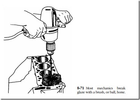
Most mechanics use a brush hone, sized to cylinder diameter, such as the 120-grit BRM Flex-Hone pictured in Fig. 8-71. Obtaining the desired Crosshatch pattern
(shown earlier in Fig. 8-37) depends on a four-sided relationship among the ring material, spindle speed, bore diameter, and stroke frequency. For what it is worth, chrome rings running in a 4-in. cylinder need the finish produced by a 280-grit stone, rotated 190 rpm and reciprocated 70 times a minute. Such precision is unobtainable, but a little practice will produce an acceptable surface.
It is important to use plenty of lubricant, such as mineral oil or PE-12, available in aerosol cans from specialty tool houses. Keep the hone moving—it cuts as it rotates—and do not pause at the ends of the strokes. Hone for 3 or 4 seconds and stop to inspect the bore. Crosshatched grooves should intersect at angles of 30–45° relative to the bore centerline. If the pattern appears flat, reduce the spindle speed or increase the stroke rate. The job should require no more than 15 or 20 seconds to complete. Withdraw the hone while it is still turning.
Few mechanics take the time to clean a bore properly. Solvents merely float abrasive hone fragments deeper into the metal. Detergent, hot water, and a scrub brush are the prescription. Scrub until the suds are white, and wipe dry with paper shop towels. Continue to scrub and wipe until the towels no longer discolor. According to TRW, half of early ring failures can be traced to abrasive particles left in the bore.
Laying the crank
This discussion applies to engines with two-piece main-bearing shells; full-circle bearings require a slightly different technique, as outlined in the appropriate shop manual.
1. Although it is late in the day, make one final inspection of the block.
Critical areas include saddle alignment for two-piece GM block castings, cracks that are likely to be associated with saddle webbing and liner flanges, and main bearing cap-to-saddle fits. Most caps are buttressed lat- erally by interference fits with their saddles. Fretting on contact surfaces can, if not corrected, result in crankshaft failure. Some mechanics make it a practice to chase main-bearing bolt threads; if you opt to do this, use the best, most precise tap that money will buy.
2. Verify that main-bearing saddles are clean and dry.
3. Unwrap one set of main-bearing inserts. Bearing size will be stamped on the back of each insert. All machinists can tell stories about mislabeled bearings, but certainly it would give one pause if the crankshaft were turned 0.010 in. and the inserts were marked “Std.”
4. Identify the upper insert, which always is ported for crankshaft lubrication. A few lower shells carry a superfluous port; most are blanked off and grooved.
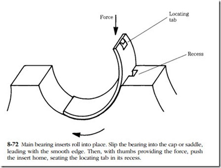
5. Roll the upper insert into place on the web, leading with the locating tab, as shown in Fig. 8-72. Make absolutely certain that the tab indexes with the web recess. When installed correctly, the ends of the insert stand equally proud above the parting face.
6. Verify that the oil passage drilled in the web indexes with the oil port in the insert. A glance will suffice, but some shops go a step further and run a drill bit through the insert and into the web.
7. Install the remaining upper shells, one of which might be flanged for thrust. Check each insert for indicated size and, once they are installed, verify that oiling passages are open.
8. Where appropriate, install the upper half of the rear crankshaft seal, per manufacturer’s instructions. Rope seals must be rolled into place, using a bar sized to match crankshaft journal diameter.
9. Saturate the bearings and seal with clean lube oil. (Some mechanics prefer to use a grease formulated for bearings assembly, such as Lubriplate No. 105. Grease is very appropriate when the engine will not be returned to immediate service.)
10. Wipe down the crankshaft with paper shop towels. Coat journals and crankpins with a generous amount of lubricant.
11. Lower the shaft gently and squarely into position on the webs. Exercise care not to damage thrust flanges.
12. Install lower bearing shells into the caps, lubricating as before.
13. Mount the caps in the correct orientation and sequence. Lightly oil cap bolt threads.
14. Torque the caps, working from the center cap outward. Conventional bolts make up in three steps—1/3, 2/3, and 3/3 torque; torque-to-yield bolts are run down to a prescribed torque limit and rotated past that limit by a set amount. After each cap is pulled down, turn the crankshaft to detect possible binds.
• Radius ride, a condition recognized by bright edges on the bearing shells and caused by excessively large crankshaft fillets left after regrinding. Return the crankshaft to the machinist.
• Dirt on the bearing face or OD.
• Insufficient running clearance, a condition that can be determined with Plasti-Gage (see below).
• Bent crankshaft or misaligned bearing saddles.
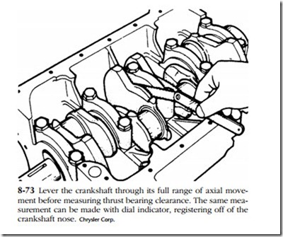
15. Using a pry bar, lever the crankshaft toward the front of the engine, then pull back (Fig. 8-73). Measure crankshaft float with a feeler gauge between the thrust bearing face and crankshaft web.
Piston and rod installation
It is assumed that piston and rod assemblies have already been made up. If the machinist has not already done so, install the rings on the piston. Rings are pack- aged with detailed instructions, which supersede those in the factory manual. Here, it is enough to remind you that:
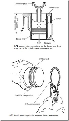
• The time required to check ring gap is well spent, because rings, like bearing inserts, are sometimes mislabeled. Using the flat of the piston as a pilot, insert each compression ring into the cylinder and compare ring gap with the specification (Fig. 8-74).
• Ring orientation is important; according to one manufacturer, a reversed scraper ring increases oil consumption by 500%.
• Using the proper tool, expand the ring just enough to slip over the piston (Fig. 8-75).
• Stagger ring gaps, as detailed by the manufacturer.
At this point, you are ready to install the piston assemblies. Follow this procedure:
1. Remove the bearing cap from No. 1 rod and piston assembly
2. Mount an upper bearing shell on the rod, indexing oil ports.
3. Coat the entire bearing surface with fresh lube oil. Repeat the process for the cap.
4. Slip lengths of fuel line over the rod bolt ends to protect the crankshaft journals during installation.
5. Turn the crankshaft to bottom dead center on No. 1 crankpin. Saturate the crankpin with oil.
6. Install a ring compressor over the piston. The bottom edge of the com- pressor should be a 1/2 in. or so below the oil ring. Tighten the compressor bands just enough to overcome ring residual tension.
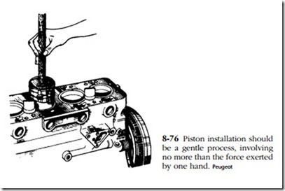
7. With the block upright and the leading side of the piston toward the front of the engine, place the compressor and captive piston over No. 1 cylinder bore. A helper should be stationed below to guide the rod end over the crankpin. While holding the compressor firmly against the fire deck, press the piston out of the tool and into the bore. As shown in Fig. 8-76, thumb pressure should be sufficient. Stop if the piston binds and reposition the piston in the compressor.
8. Install the lower bearing shell in the cap; verify that the locating tab indexes with its groove.
9. Coat the bearing contact surface with lube oil.
10. Working from below, carefully remove the hoses from the bolt ends and pull the rod down over the crankpin. Make up the rod cap, making sure match-marks align.
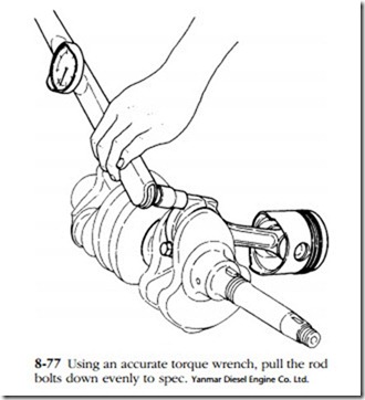
11. Torque the rod bolts to spec (Fig. 8-77).
12. Using a hammer handle or brass knocker, gently tap the sides of the big end journal. The rod should move along the length of the crankpin.
13. Rotate the crankshaft a few revolutions to detect possible binds and the bore scratches that mean a broken ring. Resistance to turning will not be uniform: piston speed increases at mid-stroke, with a corresponding increase in crankshaft drag.
14. Repeat this operation for remaining pistons.
15. Press or bolt on piston cooling jets, aiming them as the factory manual indicates.
Plastigage
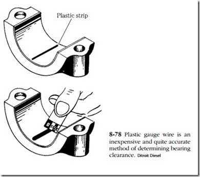
Old-time mechanics checked timing gears by rolling a piece of solder between the gear teeth. The width of the solder represented gear lash. (This technique has generally been replaced by direct measurement with a dial indicator.) Plastic gauge wire represents an application of the same principle to journal bearings. Perfect Circle and several other manufacturers supply color-coded gauge wire together with the necessary scales that translate wire width into bearing clearance. Green wire responds to the normal clearance range of 0.0001–0.0003 in.; red goes somewhat higher—0.0002–0.0006; blue extends to 0.0009 in. Accuracy compares to that obtained with a micrometer.
1. Remove a bearing cap and wipe the lubricant off both the cap and the exposed portion of the journal.
2. Lay a strip of gauge wire longitudinally on the bearing, about 1/4 in. off-center, as shown in Fig. 8-78.
Note: Invert the engine or raise the crankshaft with a jack under an adjacent counterweight before gauging main-bearing clearances. Otherwise, the weight of the crankshaft and flywheel will compress the wire and give false readings.
3. Assemble the cap, torquing the hold-down bolts to specifications.
4. Without turning the crankshaft, remove the cap. Using the scale printed on the gauge-wire envelope, read bearing clearance as a function of wire width. Clearance should fall within factory assembly specifications. If it does not, remove the crankshaft and return it to the machinist. Scrape or wipe off the gauge wire with a rag soaked in lacquer thinner. Reoil the bearing and journal before final assembly.
Balancing
Precision balancing is an optional service, difficult to justify in economic terms, but worth having done if the goal is to build the best possible engine. Balanced engines run smoother, should last longer, and sometimes exhibit a small gain in fuel economy.
But do not expect wonders; balancing is a palliative, arrived at by compromise, and effective over a fairly narrow rpm band. No amount of tweaking can take all of the shake, rattle, and roll out of recip engines.
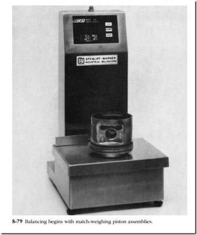
There are three steps in the balancing process. First the technician equalizes piston and pin weights to within 11/2 g (Fig. 8-79). If the technician works out of a large inventory, this can sometimes be achieved by selective assembly. Otherwise, machine work is in order; heavy pistons are lightened by turning the inner edge of
the skirts, and when absolutely necessary, aluminum slugs can be pressed into the hollow piston pins to add weight to light assemblies.
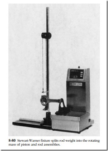
The next step is to match-weight the rods using a precision scale and a special rod adapter, such as shown in Fig. 8-80. The Stewart-Warner adapter makes it pos- sible to distinguish between rotating (or lower-end) and reciprocating (upper-end) masses; when such equipment is not available, the technicians assume that the lower half of the rod rotates and that the upper end describes a purely reciprocating path. However arrived at, rod reciprocating and rotating masses are equalized to a 11/2 g tolerance by removing metal from the balance pads (shown as the extensions on the ends of the DDA rod in the photograph and more clearly back in Fig. 8-59, where they are labeled “noncritical” areas).
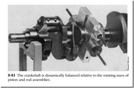
The technician computes the total rotating mass and bolts an equivalent mass to the crankshaft (Fig. 8-81). The shaft is then mounted on the balancer and rotated at the desired speed, which should correspond to actual operating conditions. Balance, or matching counterweight mass to rotating mass, can normally be achieved by drilling the counterweights. Most shops work to a 0.5 oz.-in. tolerance; the equipment will support 0.2 oz.-in. accuracy. Once this is done, the process is repeated for the harmonic balancer and clutch assembly.
Oil seals
Oil seals can be a headache, especially if one leaks just after an overhaul. Premature failure is almost always the mechanic’s fault and can be traced to improper installation.
Rope or strip seals are still used at the aft end of the crankshaft on some engines. These seals depend on the resilience of the material for wiping action and so must be installed with the proper amount of compression. Remove the old seal from the grooves and install a new one with thumb pressure. (You might want to coat the groove—but not the seal face—with stickum.) The seal should not be twisted or locally bound in the groove.
Now comes the critical part. Obtain a mandrel of bearing boss diameter (journal plus twice the thickness of the inserts) and, with a soft-faced mallet, drive the seal home. Using this tool as a ram, you can cut the ends of the seal flush with the bearing parting line. Without one of these tools you will have to leave some of the seal pro- truding above the parting line in the elusive hope that the seal will compact as the caps are tightened. Undoubtedly some compaction does take place, but the seal ends turn down and become trapped between the bearing and cap, increasing the running clearance. Lubricate the seal with a grease containing molybdenum disulfide to assist in break-in.
Synthetic seals, usually made of Neoprene, are used on all full-circle applications and on the power takeoff end of many crankshafts as well. These seals work in a manner analogous to piston rings. They are preloaded to bear against the shaft and designed so that oil pressure on the wet side increases the force of contact.
These seals must be installed with the proper tools. If the seal must pass over a keyway, obtain a seal protector (a thin tube that slides over the shaft) or at least cover the keyway with masking tape. Drive the seal into place with a bar of the cor- rect diameter. The numbered side is the driven side in most applications. The steep side of the lip profile is the wet side. It is good practice to use a nonhardening sealant on the back of metallic seals. Plastic coated seal cams are intended to con- form to irregularities in the bore and do not need sealant.
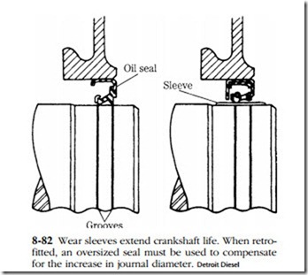
More elaborate seals require special one-of-a-kind factory tools. The better engines often incorporate wear sleeves over the shafts, either as original equipment
or as a field option. Figure 8-82 shows the use of a wear sleeve on a Detroit Diesel crankshaft. The sleeve makes an interference fit over the shaft and is further secured with a coating of shellac. Worn sleeves are cut off with a chisel or peened to stretch the metal. The latter method is preferred because there is less chance of damaging the shaft.
