Prospective SMES Applications Toward Smart Grids
7.1 Application Solutions of SMES in the Modern Power Systems
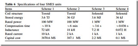
To cope with modern power systems, large-scale, medium-scale, and small-scale SMES devices with different energy storage capacity and power rating are demanded. In this section, four SMES units as shown in Table 6 are introduced to
discuss and verify the application schemes and characteristics of SMES for power generation, transmission, distribution, and end-users.
Analysis on Daily Load Levelling
Daily load leveling refers to the use of electric energy stored in the large-scale ESSs during the time periods of low demand to supply peak demand. Large-scale pumped hydro storage (PHS) technology with a typical storage efficiency between 70 and 80 % is currently the commercial storage option for daily load leveling. It has been reported [66] that a TJ-class SMES device with high storage efficiency of *90 % and no site limitation will be a promising solution in the future. Although the capital cost of a SMES device is more than that of a PHS device with the same capacity at present, SMES will reduce the annual operation cost for the same capital cost to 50–60 % of that of PHS, thus the overall life cycle cost of SMES may be lower than that of PHS.
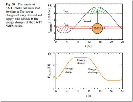
Figure 38 shows a typical curve of a 3.6 TJ SMES device for daily load leveling: (i) During the low demand time periods, the 3.6 TJ SMES device in Scheme 1 is operated at energy charge state to absorb the surplus power Pmin Pdemand, and thus the base-load power plants can be operated efficiently at full power Pmin; (ii) During the peak demand time periods, the 3.6 TJ SMES device will be operated at energy discharge state to release the stored energy to com- pensate the shortfall power Pdemand – Pmax for satisfying the real-time load power demand Pdemand, which reduces the need to draw an electricity from the peaking power plants or increase the grid infrastructures; (iii) During the medium-demand time periods, the practical electricity generated Pgenerated can basically follow with the Pdemand, and the 3.6 TJ SMES device is operated at energy storage state with nearly zero energy loss.
The energy practically stored in the 3.6 TJ SMES device fluctuates along with the dynamic energy exchange processes, and can be calculated by
leveling. a The power changes of daily demand and supply with SMES; b The energy changes of the 3.6 TJ SMES device
where E0, initial stored energy; Pr(t), the surplus or shortfall power. In the case of sinusoidal AC power and energy exchange, Pr(t) approximately equals to the root mean square (RMS) power PRMS due to the equivalence of the AC to DC power conversion, thus the absorbed or released energy equals to the product of PRMS and time duration Dt.
Since the 3.6 TJ SMES device can be controlled to fully compensate the reference power demand when ISMES(t) is greater than or equal to the RMS current IRMS, the maximum compensation time duration can be calculated by
where Imax is the maximum allowable operation current through the HTS coil, which should be limited within its critical current to avoid the occurrence of quench.
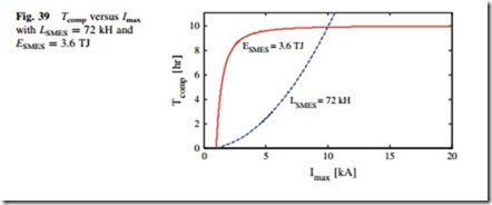
Figure 39 shows the results of Tcomp versus Imax with LSMES = 72 kH and ESMES = 3.6 TJ. For a specific coil inductance, Tcomp is almost proportional to the square of Imax. For a specific energy storage capacity, Tcomp increases rapidly with increment of Imax at first and then approaches a saturation value gradually. A reasonable parameter optimization should be achieved by considering the external power demands and development specifications of the HTS coil, e.g., the capital
cost [67] for developing a large-scale HTS coil with large coil inductance, the refrigeration cost [68] for achieving a ultra-low operation temperature with high critical current. What is more, the coil structure should also be optimized to reduce the electromagnetic force and stray magnetic field for further improving the critical current and lessening the electromagnetic pollutions. The multipole solenoidal coil [33] and toroidal coil [14] are normally applied at present. Recently, three new kinds of force-balanced coil (FBC) [69], stress balanced coil (SBC) [70], and tilted toroidal coil (TTC) [71] have been introduced for large-scale coil developments.
Analysis on Load Fluctuation Compensation
As mentioned above, a TJ-class SMES or PHS device is available for daily load leveling. However, there are still some second-level or minute-level load fluctuations during the medium-demand time periods. A GJ class SMES device seems to be a more economical option for these load fluctuation compensation applications in the power transmission systems. Currently, two ongoing 2.4 GJ YBCO SMES [14] and 48 GJ MgB2 SMES [42] projects are proposed to carry out the load fluctuation compensations from hundreds of MW to GW class.
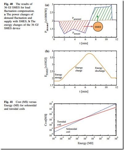
Figure 40 shows the results of SMES for minute-level load fluctuation compensations. Since SMES has the shortest response time to absorb or release the electricity as compared to other ESSs, the introduction of the 36 GJ SMES device in Scheme 2 makes the dynamic compensation more effective and timely.
The relations between the capital cost and energy storage capacity in a SMES device are shown in Fig. 41, and the capital cost equations [67] for a solenoidal coil and toroidal coil can be approximatively expressed by Cost (M$) = 0.95 [Energy (MJ)]0.67 and Cost (M$) = 2.04 [Energy (MJ)]0.5.
The capital costs of the 3.6 TJ and 36 GJ SMES coils are 3870.6 and 387.1 M$, respectively. To reduce the capital cost and make better use of a SMES device, the SMES can be introduced to combine with other ESSs for forming a hybrid energy storage system (HESS). The HESS has very high reliability because the hybrid combinations of several ESSs can combine to use their advantages in full, but fluctuation compensation. a The power changes of demand fluctuation and supply with SMES; b The
compensate for each other’s disadvantages. A typical case is the LIQHYSMES storage unit (LSU) [42] consisting of 125 GWh LH2 energy and 48 GJ SMES, which has the advantages of fast response speed, high power density, and high energy density. Therefore, the 36 GJ SMES device can be used not only for short- time load fluctuation compensations, but also for daily load leveling by combining with a large-scale PHS device. The above HESS concept provides an economical way for smart power generation and transmission management.
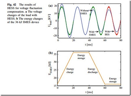
Fig. 42 The results of HESS for voltage fluctuation compensation. a The voltage changes of the load with HESS; b The energy changes of the 36 kJ SMES device
Analysis on Voltage Fluctuation Compensation
Since the power density of SMES is about 100 times higher than that of a redox flow battery, and about 10 times higher than those of a lead-acid battery and NaS battery [72], SMES can provide much larger exchanging power as compared to the battery energy storage (BES) for the same mass and volume. Moreover, the grid voltage fluctuations can be compensated within a quarter of power-frequency cycle because the response time of SMES is generally about 1–5 ms, however, the first cycle compensation cannot be practically achieved with BES. Therefore, a number of MJ-class and MW-level SMES devices [34–41] have been developed in the world for the studies of the potential replacement of BES in the power distribution systems.
According to (12), Tcomp equals to several seconds for the MW-level fluctuation compensations if the 3.6 MJ SMES device in Scheme 3 is applied. To further enlarge Tcomp, a larger energy storage capacity is needed. For instance, the 36 GJ SMES device in Scheme 2 can bring a very large Tcomp of about 9 h, however, the high capital cost makes the scheme uneconomical. In view of the economy and practicability of the current SMES technology, some small-scale HESSs [13, 30, 31] have been studied and verified that the introduction of SMES with fast response speed and high power density can improve the dynamic performance of HESS, especially for solving ms-level power quality problems. Figure 42 shows the results of a typical SMES-BES HESS for voltage fluctuation compensations.
The 36 kJ SMES device in Scheme 4 is only applied to absorb or release 20 kJ electric energy to compensate the 1 MW voltage swell or sag within the first 20 ms, and then the BES will continue to carry out the voltage fluctuation compensations for a much longer time.
Application Prospects and Considerations of SMES in Future Smart Grid The alternatives for the continued availability of a highly reliable and inexpensive power supply in future SGs include the deployment of clean coal generation, nuclear power generation, renewable energy generation, and other generation resources. Various ESSs can be used to allow increased capacity and stability to be derived from any given quantity of physical resources, and should be considered as a strategic choice that allows for optimum use of existing and new resources of all kinds. The overview and application analyses of the current SMES technology conclude that SMES has the significant potential to combine with, and even replace other ESSs in modern power systems. It is expected that the future SMES devices are not only essential to improve the power quality with small-scale or medium-scale energy storage capacity but also ensure the daily load leveling and overall reliability of the power systems with large-scale energy storage capacity.
Application Prospects of SMES in Future Smart Grids
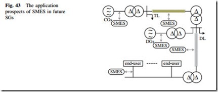
Figure 43 shows the application prospects of SMES for future SGs [73]. The main SMES application schemes and their basic functions are described as follows:
(i) SMES installed near the large-scale centralized generators (CGs) is used to balance the output power and to achieve daily load leveling; (ii) SMES installed in the transmission lines (TLs) is used to form FACTS devices for compensating the load fluctuations and maintaining the grid frequency stability; (iii) SMES installed
in the distribution lines (DLs) is used to form DFACTS devices for improving the power quality; (iv) SMES installed near the DGs is used to reduce the impacts from the intermittent RESs and to facilitate the grid integration; (v) SMES installed near the power end-users is used to form SMES-based UPSs for enhancing the stability of electricity and protecting the critical loads.
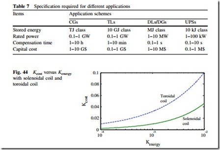
The requirements of a single SMES unit in the above five application schemes are shown in Table 7. Besides the application solution of sole SMES with full energy storage scale, three additional application solutions of SMES should be considered in future SGs.
The first solution is to install a number of SMES devices with very high power rating and very low energy storage capacity near the commercial ESS devices for forming an SMES-based HESS. As compared to the application solution of sole SMES, SMES in a HESS is only used to compensate the initial fluctuations of electricity for a very short-time period. For instance, the 10 GJ class SMES can be used to carry out the daily load leveling for a few minutes before the initial operation of large-scale PHS, and to compensate some rapid load fluctuations during the whole day. The 10 kJ class SMES can be used to improve the power quality and stability for one or a few power-frequency cycles before the initial operation of medium-scale BES.
The HESS technology will greatly reduce the capital cost of ESSs in different power system applications. Figure 44 shows the results of Kcost versus Kenergy with solenoidal coil and toroidal coil. Kenergy is the ratio between the SMES energy storage capacity needed in a HESS and the energy storage capacity in a sole SMES.
Kcost is the ratio between the SMES capital cost needed in a HESS and the capital cost in a sole SMES. It is noticed that Kcost & 0.1 when Kenergy = 0.01 for large- scale toroidal coil developments, and Kcost & 0.45 when Kenergy = 0.01 for medium-scale and small-scale solenoidal coil developments.
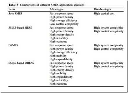
The second solution is to distribute several small-scale SMES units in different locations and to make all the SMES units work harmoniously by combined control of each SMES. This so-called distributed SMES (DSMES) technology has already been commercially deployed and operated [74]. The DSMES technology has the advantages of high mobility and high expandability because the SMES units in the trucks are easy to install in arbitrary locations once they arrives on site. The results reported [43] indicate that the DSMES technology behaves better in performance than the concentrated installation of a large-scale SMES unit.
The third solution is to combine the HESS and DSMES technologies and to distribute a number of HESS units in large, medium, and small scales for the power generation, transmission, distribution, and end-users. The distributed HESS (DHESS) technology having the advantages of both HESS and DSMES will provide very efficient stability and reliability of the whole power system.
The comparisons of different SMES application solutions are shown in Table 8. The three improved solutions utilize various ESS devices and technologies efficiently and enhance the flexibility and economy of SMES greatly. Therefore, it can be expected that SMES will be a flexible and efficient ESS option for smart power and energy managements in future SGs.
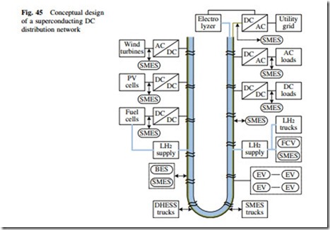
Conceptual Design of a Superconducting DC Distribution Network with Superconducting DC Cable and SMES Technologies The resistive energy losses consumed on power transmission lines become enor- mous as the high-capacity of power demand is required by the dramatically expanding and developed society. HTS technology is an alternative way to resolve the conventional difficulties to achieve high efficiency in power transmissions [7, 8]. The superconducting DC cable with nearly zero energy loss is favorable for low-voltage and long-distance power transmission for future power end-users. Various SMES devices with different application schemes have the potential to further enhance the stability and reliability of the superconducting DC transmissions. Figure 45 shows the conceptual design of a superconducting DC distribution network with superconducting DC cable and SMES technologies. The superconducting DC distribution network is to implement the hybrid energy transfer of the hydrogen and electricity, which has been technically verified [75–77]. The LH2 transferred can not only be used to provide hydrogen energy for the fuel cells (FCs) and FC vehicles (FCVs) [17], but also be used as the refrigeration fluid for cooling the superconducting DC cable and SMES devices, which can be developed by either HTS YBCO wires or MgB2 wires.
The application schemes of SMES in the superconducting DC distribution network are described as follows: (i) SMES and HESS devices installed in the
cable terminal and middle parts are used to enhance the power transmission capacity and to maintain the voltage stabilization; (ii) DSMES and DHESS trucks with highly mobile and expandable characteristics are used to further improve the integrated performance of scheme (i) in arbitrary locations or time periods;
(iii) SMES devices installed in the DC bus of local PV cells or FCs are used to maintain the output voltage stabilization for connecting with the DC distribution network and improving the reliability of electricity in off-grid loads; (iv) SMES devices installed near the on-grid loads are used to serve as fast response and high power UPSs; (v) SMES devices installed in FCVs are used to enhance the fast repeated charge–discharge performance and further to enhance the reliability of the vehicle-to-grid (V2G) [78] and vehicle-to-building (V2B) technologies [79].
The superconducting DC distribution network is able to operate with very high current density and very low voltage allowing direct connection of the generators to the local power end-users, eliminating the need for high voltage insulation and transformers. For the same power delivery as in the typical 110–1000 kV conventional transmission system, if a superconducting DC cable with the operation current ranging from thousands of amperes to tens of thousands of amperes is applied, the operation voltage might be greatly reduced to thousands of volts.
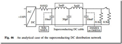
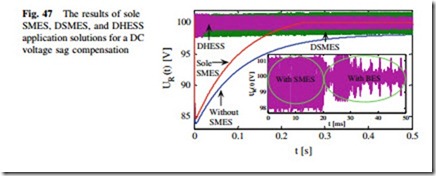
Figure 46 shows an analytical case of the superconducting DC distribution network. A 110 V rectified DC power source is applied to a 0.1 X load resistor through the superconducting DC cable. The energy lossy resistor from the relevant power electronic devices is assumed as 0.01 X. If an additional 0.5 X load resistor is connected in parallel from the time zero, the operation voltage across the two load resistors will decrease rapidly to about 83 V at first and then increase gradually to about 97 V, as shown in Fig. 47.
To maintain the practical operation voltage around their reference value of 100 V, three SMES application solutions are adopted. The first one is to install a 2 H/300 A sole SMES unit near the DC power source. The sole SMES unit can be used to compensate the dynamic load fluctuations in different superconducting DC cables, however, the inductive and capacitive reactance from the long-distance cable limits the practical response speeds. As shown in Fig. 47, there is still an inevitable voltage drop from 0 to about 0.24 s.
The second one is to distribute several DSMES units in different cables or in different locations along a specific cable. The DSMES unit located at the terminal of a superconducting DC cable in Fig. 46 can be directly applied to compensate the voltage sag within several milliseconds, which results in an effective and timely voltage sag compensation process.
The third one is to combine the small-scale DSMES units with several local ESSs, e.g., BES, to form a DHESS. The DSMES unit is only applied to compensate the voltage sag within the first 20 ms, which reduces the energy storage capacity and capital cost of the DSMES units.
Acknowledgments The author thanks X. Y. Chen who assisted this work, and also the support from Y. Xin, Y. G. Guo, J. G. Zhu, and C. Grantham.
