SMES Application Topologies and Performance Evaluations
With the development of micro grids (MGs) and smart grids (SGs), it is expected that combination of centralized power generation and distributed power generation for developing modern resource-saving and environment-friendly power systems will occur in future. The ultimate purpose is to satisfy the increased power quality requirements from modern power consumers. Fast response, high efficiency, large- scale energy storage systems (ESSs) play an important role for smart regulation and control in flexible AC transmission systems (FACTS) for power transmission, distributed flexible AC transmission systems (DFACTS) for power distribution, and widespread renewable energy sources (RESs) penetration and replacement of the current fossil-fuel power generation. This section summarizes the application topologies and evaluates the high-performance SMES devices for power grid applications.
Basic VSC and CSC Application Topologies
VSC-Based SMES
Figure 22, as an example, shows the basic configuration of a VSC-based SMES unit [57], which consists of a Wye-Delta transformer, a six-pulse pulse width modulation (PWM) rectifier/inverter using insulated gate bipolar transistor (IGBT), a two-quadrant DC–DC chopper using IGBT, and a superconducting coil or inductor. The PWM converter and the DC–DC chopper are linked by a DC-link capacitor.
The PWM VSC provides a power electronic interface between the AC power system and the superconducting coil. The control system of the VSC is shown in
Fig. 23. The proportional-integral (PI) controllers determine the reference d- and q-axis currents by using the difference between the DC-link voltage EDC and reference value EDC_ref, and the difference between terminal voltage VG and ref- erence value VG_ref, respectively. The reference signal for VSC is determined by converting d- and q-axis voltages which are determined by the difference between reference d–q axes currents and their detected values. The PWM signal is generated for IGBT switching by comparing the reference signal which is converted to a three-phase sinusoidal wave with the triangular carrier signal. The DC voltage across the capacitor is kept constant throughout by the six-pulse PWM converter.
The superconducting coil is charged or discharged by a two-quadrant DC–DC chopper. The DC–DC chopper is controlled to supply positive (IGBT is turned ON) or negative (IGBT is turned OFF) voltage Vsm to the SMES coil and then the stored energy can be charged or discharged. Therefore, the superconducting coil is charged or discharged by adjusting the average voltage Vsm_av across the coil which is determined by the duty cycle of the two-quadrant DC–DC chopper. When the duty cycle is larger than 0.5 or less than 0.5, the stored energy of the coil is either charging or discharging, respectively. In order to generate the PWM gate signals for the IGBT of the chopper, the reference signal is compared with the triangular signal.
CSC-Based SMES
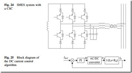
Figure 24, as an example, shows the basic configuration of a current source converter-based (CSC-based) SMES unit. The DC side of CSC is directly connected with the superconducting coil, and its AC side is connected to the power line. A bank of capacitors connected to a CSC input terminal is utilized to buffer the energy stored in line inductances in the process of commutating direction of AC line current. Furthermore, the capacitors can filter the high-order harmonics of the AC line current. In the CSC, through regulating the trigger signals of the switching devices, the current in the superconducting coil can be modulated to generate controllable three-phase PWM current at the AC side. As the SMES system is inherently a current system, the transfer of both active and reactive powers between the CSC and power network is very fast.
In case of a 12-pulse CSC-based SMES, to improve the total harmonics distortion (THD) of the ac source currents, an optimal PWM switching strategy is used to minimize the 5th, 7th, 11th, and 13th harmonics. It has been proved that the 5th, 7th, 11th, and 13th harmonics can be minimized to zero with the modulation index ranging from 0.2 to 1. Compared to a 6-pulse CSC, the 12-pulse CSC has smaller voltage ripples on the dc side, which means a further reduction of the ac losses in the SMES coil.
For magnet training, a DC current Id control algorithm is applied. The block diagram is shown in Fig. 25, where Idref is the reference value of Id, PI is a proportional-integral regulator, L is the inductance of the SMES coil, Rd is the resistance in the DC circuit, and Vd is the DC voltage. With the phase angle a being fixed to zero, the DC voltage is proportional to the modulation index M, which determines the charging rate.
Integrated Application Topologies in Power Grids
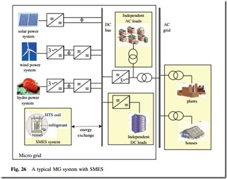
Application Topologies in Distributed Generators and Micro Grids To reach widespread RESs penetration and replacement of the current fossil-fuel power generation, an innovative concept of micro grid (MG), which integrates several DGs and distributed ESSs, has been proposed to achieve large power quality improvements and comprehensive utilizations of various local DGs. A typical MG system with a SMES is shown in Fig. 26 [30, 31]. The generated power of the solar power system, wind power system, and hydro power system are
gathered in the DC bus through several power conversions. The SMES system carries out dynamic power exchange with the DC bus to maintain the power stabilization in DC bus. The MG system can be applied as a power supply for independent loads and grid loads.
There are three main technical advantages in the MG system with a SMES:
(i) SMES with rapid response characteristics (ms level) can, such as voltage interrupt, instantaneous voltage dip, etc.; (ii) SMES with very large power output characteristics (MW level) can provide enough compensation power for DC bus;
(iii) SMES with very high energy storage efficiency characteristics can improve the operation efficiency in the whole MG system.
Application Topologies in Transmission and Distribution Systems To solve different power quality problems, e.g., voltage sag, voltage swells, voltage fluctuation, interruptions, harmonics, etc., various power conversions, compensation, and control devices have been introduced to regulate and control the transmission and distribution systems. The main solutions for various power
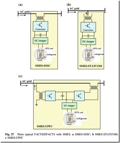
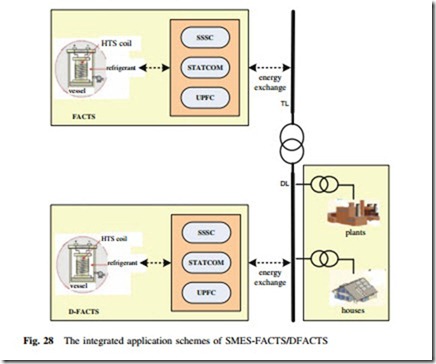
quality problems include FACTS for the power transmission side and DFACTS for the power distribution side. Three basic FACTS and DFACTS devices, i.e., series- type static synchronous series compensator—SSSC, static synchronous compensator—STATCOM, unified power flow controller—UPFC, with a SMES unit in the device, are shown in Fig. 27. The integrated application schemes of SMES- FACTS/DFACTS in power transmission line (TL) and distribution line (DL) are shown in Fig. 28.
Integrated Application Topologies in Smart Grids
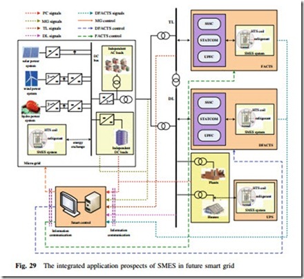
Based on the above discussions, the prospect of SMES in future SG is proposed in Fig. 29. In addition to the traditional power generation plants including hydro power plants, thermal power plants, and nuclear power plants, various MGs or DGs using RESs will be widely installed in future SGs. With the dynamic power exchange and regulation from SMES or hybrid ESSs, MGs or DGs can be directly connected to the main power transmission and distribution lines (DLs). SMES- based FACTS and DFACTS devices can be further applied to carry out the whole power flow control for reaching the increasing power demands from modern power consumers (PCs). The real-time signals in the whole SG will be transmitted to the smart control center for data processing and finally achieving the integrated power management and control of FACTS, DFACTS, and MGs. As an auxiliary power management technology, the SMES-based UPS devices installed in the power terminals will guarantee the power quality for various PCs.
Applications of SMES in Power Grids
The application topologies and advantages of SMES for MGs, transmission and distribution systems are described in this section. The application scheme of hybrid ESSs with distributed SMES devices are proposed and discussed to com- bine the advantages from SMES devices and other conventional ESSs, and to achieve better performance in practical power applications. The integrated solu- tions for SGs are proposed with functions and application schemes of SMES devices.
Applications in Distributed Generators and Micro Grids
(1) Application in wind power system
The intermittence and unpredictable nature of the wind power cause voltage and power fluctuations. The bandwidth of the wind power fluctuations is
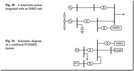
generally below 1 Hz, while the power system is more sensitive to the power fluctuations in the frequency region between 0.01 and 1 Hz. Therefore, it is necessary to smooth power fluctuations for large wind farms. Figure 30, as an example, shows a wind farm system integrated with an SMES unit, which consists of a power fluctuation suppression control module for a wind farm and a power control module for the SMES. The results obtained from the referred wind farm show that the SMES system can perform well with respect to the voltage fluctuation compensations [58].
(2) Application in photovoltaic power generation
Figure 31, as an example, shows the schematic diagram of a combined PV/ SMES system. The PV generation system and the SMES system are joined by a common bus, which is connected to the utility grid. The results obtained with or without the modulation by the PV/SMES system show that the power generated by the SMES system can be able to satisfactorily smooth out PV power fluctuations [59]. Power generated from PV arrays can be completely utilized under different weather conditions and PV penetration can be increased to significant levels without causing side effects to the power system.
(3) Application in hydroelectric power system
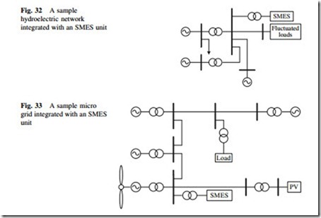
Figure 32, as an example, shows a hydroelectric network integrated with a 10 MVA/20 MJ SMES device connected to an 11 kV bus in a hydro power station [45]. The SMES is operated to compensate power fluctuation generated by the metal rolling factory near the power station. The results of a com- pensation test for the load fluctuations show that the active power fluctuation load at the bus is effectively compensated, and the active power load of the generator is almost a constant after compensation by the SMES system.
(4) Application in micro grids
Figure 33 shows a micro grid (MG) integrated with a SMES unit. The sample system includes two diesel generators, one hydro generator, one wind gener- ator, and one PV system. The SMES system is connected with the MG by a VSC [60]. The stability enhancement and minimization of frequency fluctuation of the MG can be achieved by using SMES and pitch control. Some SMES cases with different energy storage capacities and their compensation effects are discussed [60]. Simulation results show that the SMES is a very effective device for stabilization of the MG.
Applications in Flexible AC Transmission Systems
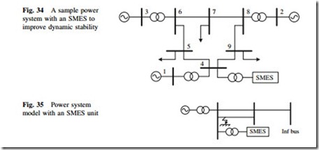
(1) Application in power system dynamic stability improvement The application of SMES for dynamic stability improvement has been studied [61]. Take a three-machine and nine-bus power system, for example, as shown in Fig. 34. The SMES system was first located between buses 4 and 9 (nearer to bus 4); then, the faults obstacles were simulated with the SMES system placed at bus 7. A three-phase ground fault was made at t = 175 s for a period of 70 ms at different locations and the total performance of the system is simulated with or without the SMES system. The results show that the rotor speed is under control while the SMES system discharges into the system as
the supply of both active and reactive power. An average active power of about 70 MW is discharged into the system during the fault at t = 175 s with a significant amount of reactive power being injected into the system simultaneously.
(2) Application in power system transient stability improvement
The application of SMES for transient stability improvement has been studied [62, 63]. The model system as shown in Fig. 35, as an example, consists of a synchronous generator and an infinite bus through a transformer and double circuit transmission line. In order to control the power balance of the synchronous generator during the dynamic period effectively, an SMES unit is located at the generator terminal bus. A fuzzy logic control method is applied to improve the transient stability and is also compared with that of a conventional PI-controlled SMES scheme. The simulation results of both balanced (three-phase-to-ground) and unbalanced (single-line-to-ground) faults demonstrate the effectiveness and validity of the SMES system for the transient stability improvements [63].
(3) Application in power system active filter
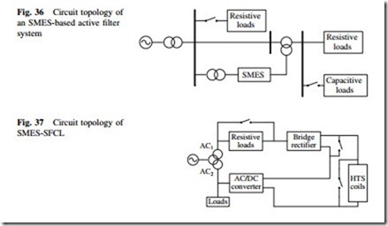
The passive filters have an increasing possibility of low degree harmonics and a limit to cover all harmonics current. However, the active filter system can reduce harmonics current at once without the problems of existing passive filter system. SMES is a very good promising source used in the active filter systems due to the high response time of charge and discharge. Figure 36, as an example, shows an SMES-based active filter system consisting of both series and shunt filter functions. The system is composed of a 3-phase DC–AC converter for compensation of harmonic current and three 1-phase DC–AC converters for compensation of voltage sag. Harmonic current from a non- linear load was assumed for confirmation of the performance of the shunt active filter. If a shunt active filter energized by SMES is applied, the harmonic elements in the utility line current are fully compensated [64].
To make full use of the HTS coils for power system applications, a promising solution is to make the superconductivity device perform more than one function, e.g., SMES and SFCL (superconducting fault current limiter), thus we can take full advantage of the device and the cost of each function is reduced effectively. Figure 37 shows the circuit topology of a typical SMES- SFCL device [65]. The combined SMES–SFCL device acts as a SMES to the AC1 system. It can alleviate voltage swells, sags, and even momentary out- ages. It also acts as a SFCL to the AC2 system and can restrain the fault current by the large inductance of the superconducting coil. When the combined device reaches its steady state, a short circuit from phase A-to-ground occurs at 1.8 s and it lasts 0.08 s. DC current in the superconducting coil and current in phase A are both monitored. The results show [65] that the fault current is effectively limited, but the coil current does not rise very much because of the existence of the part of SMES.

