Experimental Verification and Characteristics
Experimental Prototype Design
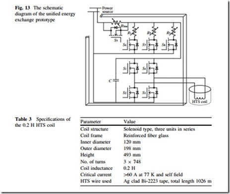
Figure 13 shows the schematic diagram of a unified energy exchange prototype for SMES study. Four Infineon N-channel MOSFETs with ultra-low turn-on resistance (Rs & 0.65 mX, under 100 A operation current) are introduced to develop the bridge-type chopper, with the power lines among the four MOSFETs formed by silvered copper bars. S1, S2, and, two reverse power diodes of S2 and S4 can be also used to form a conventional chopper for experimental tests and comparisons. The parameters of the reverse diode are Ud & 0.65 V and Rd & 2.3 mX. Thirty-two
Nichicon conductive polymer aluminum solid electrolytic capacitors with ultra- low equivalent series resistance (Resr & 11 mX) are connected in parallel to serve as the DC-link capacitor. The power-line resistor Rline is arbitrarily combined by three 0.5 X resistors. The power-load resistor Rload has three parallel resistor branches of R1, R2, and R3. The available resistors in each branch are one 1 X resistor and two 2 X resistors, and can be controlled to connect or disconnect to the power-line resistor by a MOSFET.
The HTS coil used in the experiments is a 0.2 H HTS coil wound with Bi-2223 tapes. It consists of three solenoids in series for reducing the internal connections inside the HTS coil, and is operated under liquid nitrogen (LN2) condition. The specifications of the HTS coil are shown in Table 3.
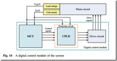
Based on the referred switching control requirements, a Micro-programmed Control Unit (MCU) was employed to build the digital control module of the system. As shown in Fig. 14, load voltage UR(t) and coil current IL(t) are sampled back to the MCU to determine the next output signals; the drive circuit mainly consisting of light coupling isolation devices to ensure the output signal from the
MCU can adequately drive the MOSFETs. The protection circuit is built based on CPLD. The protection function includes two parts: one is illegal logic protection for signals from the MCU; the other is overcurrent and overvoltage protection.
The main operation processes are described as follows: (i) Apply the power source to charge the DC-link capacitor through the power-line resistor, UR(t) increases gradually to the output voltage U of the power source; (ii) Close S1, S3 and S5, the HTS coil is charged and IL(t) increases gradually to its preset initial value I0; (iii) Open S1, and then close S2, the chopper is operated in the storage state; (iv) Open S5, and then close one, two or three branched switches of S6, S7, and S8, the corresponding branched resistors are connected to the power source through the power-line resistor; (v) The MCU and CPLD joint measurement and control unit are to implement the online voltage monitoring of UR(t) and further to change the next operation state of the chopper accordingly.
Experimental Verifications and Comparisons
Analysis on the Energy Absorption Characteristics
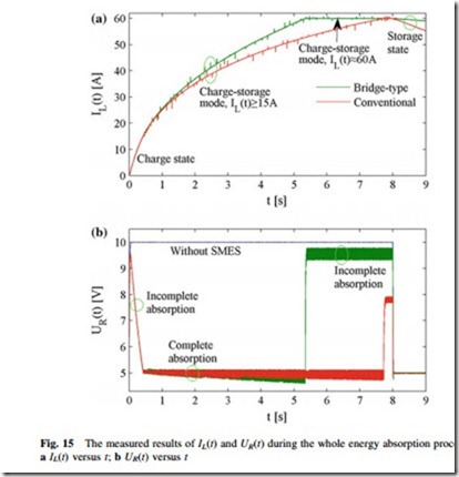
In the experiment, a DC power source U = 15 V is first applied to the power-line resistor Rline = 0.5 X and power-load resistor Rload = 0.25 X. The power-load resistor is formed by three parallel branches of R1 = R2 = 1 X, R3 = 0.5 X. Each branched resistor is operated at its rated voltage Ur = 5 V. Assume that R2 and R3 are disconnected from the time t = 0 s to t = 6 s, UR(t) will increase quickly to 10 V without SMES, and thus the remaining branched resistor R1 is operated at a voltage swell state. If the SMES is applied, the 0.2 H HTS coil should be con- trolled to absorb the mean surplus power Psu = 75 W and the mean surplus cur- rent Isu = 15 A.
Figure 15 shows the measured results of IL(t) and UR(t) during the whole energy absorption processes, which can be divided into three different segments. The first one is an incomplete absorption segment when IL(t) \ 15 A, both the bridge-type and conventional choppers will be operated at a charge state until UR(t) drops to 5 V again. The second one is a complete absorption segment when 15 A B IL(t) \ 60 A, the two choppers are operated at a charge-storage mode to maintain UR(t) around 5 V. Once IL(t) reaches its rated operation current ILr = 60 A, the third process enters into an incomplete absorption segment, and the surplus power cannot be absorbed completely. If an additional persistent current switch [26, 27] with nearly zero resistance is applied to connect with the HTS coil when its operation current reaches its rated value, the third process will be a zero absorption segment.
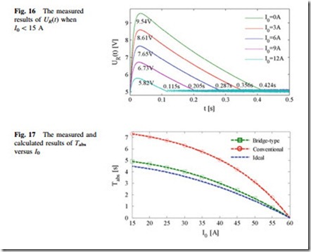
Figure 16 shows the measured results of UR(t) in the first incomplete absorption segment when IL(t) \ 15 A. If I0 \ 15 A, at the time t = 0, UR(t) will increase
quickly to a peak voltage Um, and then decreases gradually to 5 V after an incomplete absorption time duration Tm. Since the same MOSFETs S1 and S3 are used, both the bridge-type and conventional choppers have the same operation parameter in the incomplete absorption process.
In the following complete absorption segment, the maximum absorption time duration Tabs to absorb such a 75 W surplus power in the bridge-type chopper is shorter than that in the conventional one. As shown in Fig. 17, the measured results match well with the calculated results from the theoretical model, and the measured Tabs values in the bridge-type chopper are in very close proximity to the ideal values, so the bridge-type chopper has a higher energy utilization efficiency g than the conventional one. When I0 = 15 A, the measured g values are about 91.5 and 61.9 % for the bridge-type and conventional chopper, respectively. However, for a practical SMES system with a determined ILr, the conventional chopper seems to be more suitable to achieve a longer Tabs to satisfy with the external absorption demands.
Analysis on the Energy Compensation Characteristics
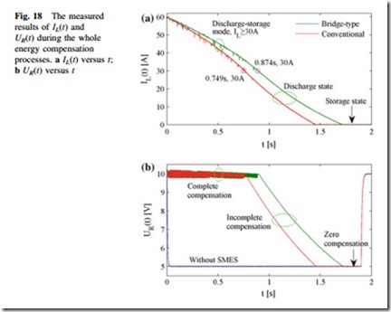
In the experiment, a DC power source U = 15 V is first applied to the power-line resistor Rline = 0.5 X and power-load resistor Rload = R1 = 1 X. The branched resistor R1 is operated at its rated voltage Ur = 10 V. Assume that R2 and R3 are connected from the time t = 0 to 1.8 s, UR(t) will decrease quickly to 5 V without SMES, and thus the three branched resistors are operated at a voltage sag state. If the SMES is applied, the 0.2 H HTS coil should be controlled to compensate the mean shortfall power Psh = 300 W and mean shortfall current Ish = 30 A.
Figure 18 shows the measured results of IL(t) and UR(t) during the whole energy compensation processes, which can also be divided into three different segments. The first one is a complete compensation segment when IL(t) C 30 A, both the bridge-type and conventional choppers are operated at a discharge-storage mode to maintain UR(t) around 10 V until IL(t) drops to 30 A. The second one is an incomplete compensation segment when IL(t) \ 30 A, the two choppers are operated at a discharge state to compensate a decreasing power. Once IL(t) drops to zero, the operation state of the two choppers should be converted into storage state to avoid the occurrence of reverse charge, and thus the third process enters into a zero compensation segment.
In the complete compensation segment, the maximum compensation time duration Tcom to compensate such a 300 W shortfall power in the bridge-type
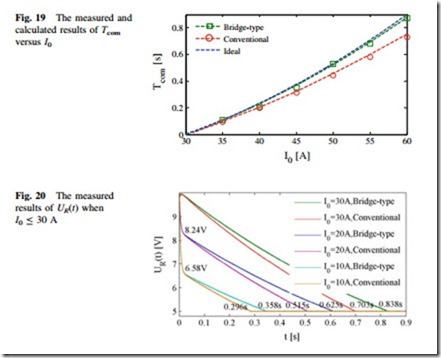
chopper is longer than that in the conventional one, as shown in Fig. 19. When I0 = 60 A, the measured g values are about 97.1 and 83.2 % for the bridge-type and conventional chopper, respectively. Furthermore, if several MOSFETs are applied in parallel to serve as a power switch, both Tcom and g can be further enlarged to approximately equal to that in an ideal chopper. However, the method to use several parallel power diodes cannot enlarge Tcom and g effectively because of the inevitable power loss from the stationary voltage drop in the conventional chopper. Therefore, the bridge-type chopper has the potential to replace the conventional one in some low-voltage power applications like a SMES-based dynamic braking drive system of an AC motor [28]. Both the absorption and compensation efficiencies for kinetic energy of the motor will be much improved. The bridge- type chopper can also be directly applied to connect the HTS coil with DC bus in a micro grid (MG) [19]. Besides the significant improvement of practical energy exchange efficiency, the practical response time to absorb or compensate the electric energy will be reduced to microsecond level, which is very beneficial to enhance the power quality with the end-user.
Figure 20 shows the measured results of UR(t) in the incomplete compensation segment when I0 B 30 A. If I0 \ 30 A, at the time t = 0 s, UR(t) will decrease quickly to a inflected voltage Uc, and then decreases gradually to 0 V after an
incomplete compensation time duration Tc. The measured Uc values in the two choppers are similar, however, the bridge-type chopper will achieve a longer Tc than the conventional one.
Analysis on the Energy Exchange Characteristics
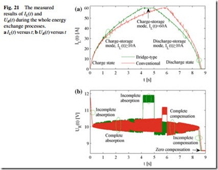
The energy absorption and compensation processes of the energy exchange proto- type have been presented independently in Sects. 4.2.1 and 4.2.2. To further discuss the dynamic energy exchange characteristics, one branch and three branches of R1 = R2 = R3 = 1 X are connected with the power-line resistor Rline = 0.5 X to achieve a power swell state and a power sag state, respectively. As shown in Fig. 21, the 0.2 H HTS coil should be controlled to absorb the mean surplus power Psu = 100 W until the time when t = 5 s in the bridge-type chopper or t = 6 s in the conventional chopper, and then to compensate the mean shortfall power Psh = 100 W until the time when t = 9 s. The whole energy exchange processes can be divided into six different segments: (i) Incomplete absorption segment when IL(t) \ 10 A; (ii) Complete absorption segment when 10 A B IL(t) \ 60 A;
(iii) Incomplete absorption segment when IL(t) & 60 A; (iv) Complete compensation segment when IL(t) C 10 A; (v) Incomplete compensation segment when 0 A \ IL(t) \ 10 A; (vi) Zero compensation segment when IL(t) = 0 A.
Similarly, the dynamic energy exchange characteristics in all the energy absorption and compensation segments can be fully obtained by integrating the theoretical and experimental studies in Sects. 4.2.1 and 4.2.2. The available parameters and data curves mainly include: (i) Um, Tm, Uc, and Tc in the incomplete absorption and compensation segments when IL(t) \ 10 A; (ii) Tabs and Tcom in the complete absorption and compensation segments when 10 A B IL(t) B 60 A;
(iii) IL(t) and UR(t) at an arbitrary time; (iv) Transient voltage, current, consumed power curves of the power-line resistor and power electronic elements.
The above operation parameters and relevant relations probably follow several power and linear functions as follows:
(i) Incomplete absorption segment, Um = -0.306I0 ? 9.514, Tm = -0.027I0 ? 0.435; (ii) Complete absorption segment, Tabs = -1.333 9 (I0)2 9 10-3 ? 4.8 in the ideal chopper, Tabs = -5.515 9 (I0)2 9 10-2.234 ? 5.157 in the bridge-type chopper, Tabs = -4.165 9 (I0)2.945 9 10-5 ? 7.285 in the conventional chopper; (iii) Complete compensation segment, Tcom = 3.333 9 (I0)2 9 10-4 – 0.3 in the ideal chopper, Tcom = 3.928 9 (I0)1.957 9 10-4 – 0.3054 in the bridge-type chopper, Tcom = 6.336 9 (I0)1.813 9 10-4 – 0.3054 in the conventional chopper; (iv) Incomplete compensation segment, Uc = 0.171I0 ? 4.853, Tc = 0.024I0 ? 0.125 in the bridge-type chopper, Tc = 0.021I0 ? 0.08 in the conventional chopper. The fitted linear and power functions have the potential to apply in practical SMES design and optimization for use in different power system applications. The proposed system also provides a feasible method to build a simple and economical test apparatus for the experimental evaluations of an SMES device before its practical applications.
Based the above theoretical and experimental results obtained, conclusions can be made as follows: As compared to the conventional chopper, the bridge-type one has higher energy utilization efficiency in various power end-user applications such as EVs, UPSs, DGs, and LVDC systems. What’s more, the energy utilization efficiency can be further improved by introducing the MOSFETs with lower applicable voltage level or adopting the multi MOSFET in parallel connection method. However, similar methods cannot improve the efficiency significantly in the conventional chopper because of the inevitable power loss from the stationary voltage drop across the two power diodes. If one simply considers the practical energy exchange effects to satisfy with the external demands, a better application scheme is to use the charge- storage mode of the conventional chopper during the energy absorption process, and to use the discharge-storage mode of the bridge-type chopper during the energy compensation process. The scheme will integrate the advantages of the two choppers for achieving very long absorption and compensation time durations.
