Detroit Diesel
Now in its sixth generation, DDEC (Detroit Diesel Electronic Control or “dee-deck”) was the first EMS designed for heavy-duty diesels. Later versions follow European practice by incorporating VGT, large amounts of EGR, and exhaust aftertreatment.
As described in more detail in Chap. 9, VGT generates boost across the whole rpm band. It also enables large amounts of exhaust gas to be recirculated under load, when EGR is needed most. Exhaust aftertreatment traps particulates and converts oxides of nitrogen, which are smog precursors, into nitrogen and water.
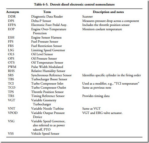
The complexity of later DDEC systems and a design philosophy that ties the product closely to service facilities severely limits what can be done without access to factory documentation and a DDR/DDL (Diagnostic Data Reader/Diagnostic Data Link). What follows pretty well sums up what a nonfactory technician, armed with a volt-ohmmeter and a generic J 1587 data-link scanner can accomplish. Table 6-5 lists Detroit Diesel nomenclature.
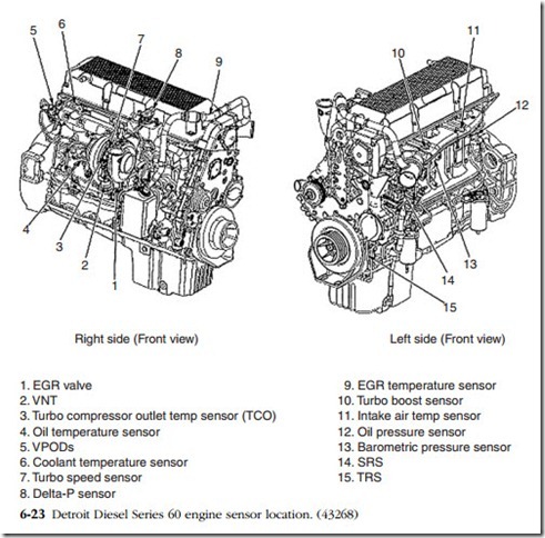
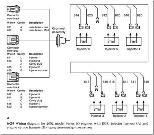
Figure 6-23 illustrates Series 60 DDEC V component locations and Figs. 6-24A and B illustrate schematics for injector and VPOD wiring. In addition to those called out in the schematics, DDEC V and VI systems incorporate sensors that monitor:
• Ambient air temperature and pressure
• EGR Delta-P and flow rate
• Turbo boost and rpm
• VGT vane position
Flash and PID codes are listed in Table 6-6.
Electronic unit injectors
Series 50 and 60 solenoid-actuated unit injectors are replaced as assemblies, using new seals, washers, and hold-down bolts. Disconnect the battery to protect the computer from voltage spikes, remove the hold-down bolt, and lift the injector free. Gentle taps with a rubber hammer should be enough to separate it from its sleeve. Kent-Moore catalogs an extraction tool (PN J47372) for stubborn cases.
If the injector is to be reused, carbon accumulations can be removed from the nozzle body with a wire brush, emory paper, or Scot-Bright. But keep abrasives clear
of the nozzle orifices. Using a hand-held brush—not a power tool—clean carbon from the sleeve and vacuum up the particles. This procedure reduces contamination of the drilled fuel passages.
Lubricate components with clean diesel fuel, and install the injector with new seals, washers, and clamp bolt, as supplied under PN 2353711 (Fig. 6-25). Note that the flat side of the copper washer goes down, toward the cylinder head. Fit the clamp over its locating pin, run the bolt down finger-tight, and
• torque the bolt to 50 N-m (37 lb-ft),
• back off the bolt 60° (one bolt flat),
• torque to 35 N-m (26 lb-ft),
• tighten the bolt 90° (one-quarter turn).
Internal fuel galleries must be flushed before starting the engine. Prime the fuel system and, with the key “off,” disconnect the ECM at the fuse box or harness
connector. Remove the combination check valve and pressure regulator, which are located at the rear of the cylinder head at the return-line elbow. Connect a hose to the gallery outlet, and crank the engine in three 15-second bursts, allowing ample time for the starter motor to cool between engagements. Once the galleries are flushed, replace the regulator, make up the fuel-return line and connect the wiring harness to the computer. Run the engine up to operating temperature and check for fuel leaks.
Detroit Diesel supplies an upgrade kit (PN 23528939) for Series 50 and 60 injectors that consists of a spring 11-mm longer than the original, a cam-follower retainer and new hold-down screws. Apparently, the original springs allowed injector plungers to “float” at high rpm. Remove the rocker-arm assembly, place it on a clean surface, and, working with one injector at a time to avoid mixing parts, remove the two 5-mm Allen screws that secure the follower retainer. Lift the retainer and the follower free (Fig. 6-26). Clean the parts in diesel fuel, and install the new spring, follower and retainer, using the screws provided in the kit. Torque to 25–28 N-m (22–25 lb-in.).
No start
Table 6-1 outlines basic troubleshooting procedures for this and other EMS- equipped engines. Trouble codes, the most critical of which are listed in Table 6-6, should help pinpoint starting problems. As far as the high-pressure fuel system is concerned, failure to start can result from:
• No voltage to the injectors. With the ignition “off,” remove the rocker covers and disconnect the ground-return wire 619 or 620 (shown back at Fig. 6-24B) from one injector. Make up a 6V test lamp between the ground wire and an engine ground. Crank the engine to verify that the injector receives voltage. Reconnect the lead and repeat the test for each of the injectors.
• Malfunctioning synchronous reference sensor/timing reference sensor. The SRS/ TRS provides the timing reference necessary to initiate and time injection (Fig. 6-27). Flash code 41 indicates that the TRS signal is missing or that the SRS generates phantom pulses. Check the security of the sensor mounting and the pulse wheel for chipped teeth or other damage. The air gap between the TRS and any pulse-wheel tooth should be .020–.040 in. Verify with a depth


