Causes of Insulation Degradation and Failure Modes of Electrical Equipment
The electrical insulation of equipment is usually made up of many different components selected to withstand the widely different electrical, mechanical, thermal, and environmental stresses occurring in different parts of the structure. The level of maintenance required for electrical equipment will depend on the effectiveness of the physical support for the insulation, the severity of the forces acting on it and the insulating materials themselves, and the service environ- ment. Therefore, the length of useful life of the insulation depends on the arrangement of individual components, their interactions upon one another, contribution of each component to the electrical and mechanical integrity of the system, and the process used in manufacturing the equipment. Historically, functional evaluation of insulation was based primarily on thermal stresses. However, with many types of equipment, other aging stresses or factors, such as mechanical, electrical, and environmental may be dominant and significantly influence service life. The following are the major causes of insulation degrada- tion and eventual failure.
Mechanical stress: Mechanical stress can be caused by power frequency transient currents such as when switching on power equipment, such as a motor or a transformer, that give rise to transient power frequency cur- rents. In the case of a motor, this transient current may be as high as six times the normal frequency current. In the case of a transformer, the power frequency current may be as high as 10–12 times the normal cur- rent. The magnetically induced mechanical forces in the equipment are the square of the transient current, therefore a motor experiences mechan- ical forces 36 or more times and a transformer experiences 100 or more times stronger than normal service. If these transient occur frequently, such as frequent starting of motors or energizing of transformers and these forces cannot be withstood it would eventually lead to mechanical damage. Also, insulation can be damaged by mechanical vibration and expansion and contraction at power frequency operation. For example, when current is applied, the end turns of motor windings are twisted. If the twisting force is strong enough to break the bond of insulating var- nish, the turns of magnetic wire will wear against each other and cause a turn-to-turn short. Once the turns are shorted, localized heating is caused by the current induced onto the closed loop. This heat rapidly degrades the surrounding insulation and over time destroys the groundwall insula- tion. A similar example may be applied to a transformer inrush current or through fault currents that can begin as mechanical damage in the turns and eventually manifest as winding faults.
Temperature hot spots: The value of temperature coefficient of resistance of an insulating material is negative and relatively large. Therefore, even a small increase in temperature will cause a large decrease in the insulation resistance. The current distribution over a given insulation is not uniform, therefore the weak part of the insulation carries more current and heated more than other parts, as long as the insulation or adjacent structures can conduct the heat away as fast as it is generated, the temperature will remain stable. However, if the heat is not dissipated as fast as it is generated the weaker spots in the insulation will become increasingly hotter until thermal breakdown occurs.
Environmental (moisture, chemicals, dirt, and oils): The environmental factors that degrade insulation over time are moisture, dirt, dust, oils, acids, and alkalies. Moisture is conductive because it contains impurities. When insula- tion absorbs or is laden with moisture it decreases the insulation resistance. The moisture penetrates the cracks and pores of the insulation, especially older insulation, and provides low resistance paths for creepage currents and potential sources of dielectric failure. Chemical fumes such as acids and alkalies often found in the industrial environment directly attack insulation and permanently lower its insulation resistance. Similarly, oil films will cover the internal surfaces of insulation of a machine. The oil may come from the environment or a leaking bearing seal. It will tend to lower the insulation resistance, reduce the ability to dissipate heat, and promote thermal aging and eventual failure. Dirt and dust in combination with moisture can become conductive and therefore cause creepage currents and insulation degrada- tion as well as reduce the ability of the insulation to dissipate heat. The life of equipment is dependent to a considerable extent upon the degree of exclusion of oxygen, moisture, dirt, and chemicals from the interior of the insulating structure. At a given temperature, therefore, the life of equipment may be longer if the insulation is suitably protected than if it were freely exposed to industrial atmospheres.
Electrical stresses (corona, surges, and partial discharges): Electrical equipment is always subjected to internally generated or external voltage and current surges. A physical rupture of insulation with the destruction of molecular bonds might occur during a voltage surge due to switching of a large induc- tive load or lightning. This transitory overpotential stresses the molecular structure of the insulating material causing ionization and failure of the insulating material itself. Corona is defined as the form of electrical dis- charge that occurs when the critical (corona inception) voltage is reached, thus causing air to breakdown. Corona by itself is not harmful to insulation however corona produces ozone which accelerates the oxidation of the organic materials of insulation. Further, the nitrogen oxides produced by the ionization of air form acids when combined with moisture also degrade the insulation. The voids in the cable-extruded insulation once electrified begin to conduct and grow larger. This phenomenon is known as partial dis- charge in the cable insulation and over time makes the void to grow larger and eventually cause cable to fail. Electrical stresses will be more significant with high-voltage apparatus or with equipment exposed to voltage transients.
Thermal aging: The temperature at which an insulation operates determines its useful life. Thermal stress is the single most recognized cause of insula- tion degradation. Insulation does not always fail when reaching some criti- cal temperature, but by gradual mechanical deterioration with time at an elevated temperature. The time–temperature relationship determines the rate at which the mechanical strength of organic material decreases. Thereafter, electrical failure may occur because of physical disintegration of the insulating materials. Typical thermal aging mechanisms include
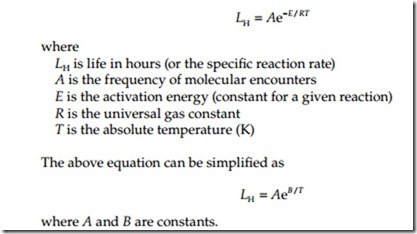
(a) loss of volatile constituents, (b) oxidation that can lead to molecular cross-linking and embrittlement, (c) hydrolytic degradation in which mois- ture reacts with the insulation under the influence of heat, pressure, and other factors to cause molecular deterioration, and (d) chemical breakdown of constituents with formation of products that act to degrade the material further, such as hydrochloric acid. The electrical and mechanical properties of insulating materials and insulation systems may be influenced in differ- ent ways and to different degrees as a function of temperature and with thermal aging. Thermal aging progressively decreases elongation to rupture so that embrittlement finally leads to cracking and that may contribute to electrical failure. Thus, how long insulation is going to last depends not only upon the materials used, but also upon the effectiveness of the physi- cal support for the insulation and the severity of the forces tending to dis- rupt it. Even though portions of insulation structures may have become embrittled under the influence of high temperature, successful operation of the equipment may continue for years if the insulation is not disturbed. Because of the effect of mechanical stress, the forces of thermal expansion and contraction may impose temperature limitations on large equipment even though higher temperature limits proved satisfactory in small equip- ment when similar insulating materials were used. The rate of physical deterioration of insulation under thermal aging increases rapidly with an increase in temperature. The oxidation of the insulating materials is a chemical reaction in which the rate of reaction is given by Arrhenius law. In his paper, “Electrical insulation deterioration treated as a chemical rate phenomenon,” AIEE Transaction, 67 (Part 1) (1948) 113–122, T.W. Dakin real- ized the relationship between the thermal aging phenomenon and the Arrhenius law of chemical reaction rates. The life of insulation is related to temperature and can be expressed by
An approximation of the above equation states that life of insulation will be reduced by half for every 10°C rise in temperature. From the above equation, it is apparent that higher the temperature, the shorter the expected life of the insulation.
Failure Modes—Electrical Power Equipment
Failures can occur in any electrical equipment at any time. The major power equipment considered for discussion are transformers, switchgear breakers, switchgear buses, electromechanical relays, cables, and rotating machines. The insulation systems makeup of the above referenced equipment contains dielectric materials which are the key components for gauging its reliability. A failure in insulation, or an insulation system, is failure of the power equip- ment. Therefore, we will briefly review the insulation systems of major elec- trical equipment and apparatus for an understanding why and how power equipment fails. A better understanding of the failure modes and effects will help broaden the understanding in the care and servicing of electrical power equipment.
Transformers
Major components that make up a transformer are primary winding, secondary winding, magnetic iron core, coolant (air, gas, oil, or synthetic fluid), bushings, and tank. The insulating materials used in the makeup of transformer insulation system are enameled conductors (wire), kraft paper, glass, thermoplastic insulating tape, presswood, glass fabric, wood, resins, porcelain, cements, polymer coatings, gasket materials, internal paints, and mineral oil or synthetic fluid. The iron core with its clamping structure, the primary and secondary windings with their clamping arrangement, and leads and tapping from windings together with their supporting structure complete the construction components of a transformer. Insulating materials used in the manufacturing of bushing are porcelain, glass, thermosetting cast resins, paper tape, and oil. The paper used in bushing is usually oil- impregnated paper, resin-impregnated paper, or resin-bonded paper. The feed-through lead conductor with its insulation system is enclosed in porcelain or glass housing. Bushings are constructed as condenser bushing or noncondenser bushing (see Section 3.6.2 for more detail). The condenser bushings are used in transformers with primary voltage rating above 50 kV whereas the noncondenser type bushings are used below 50 kV applications. Transformer failures, while infrequent, are usually the culmination of a series of events: unusual loading, impressed surges (from protective circuitry failure or local switching), or improper maintenance. Nearly always, incipi- ent failures can be determined by testing, and PM performed to correct the condition. If, however, the transformer does fault, other connected or adja- cent equipment is protected by the sensing elements and circuit breakers. Any fluid spill or fire activates the fire extinguishing system if installed. There is very little probability that even a major transformer fault will mechanically damage any equipment other than itself. The mechanical damage will largely be confined to nearby piping, support structures, or electrical connections. The possible spill of flaming transformer oil into a trench carrying either oil-filled cables, hydrogen supply lines, or the transformer oil-filtering piping could easily involve areas and elements of
equipment not electrical in nature. There is, of course, a small chance that projectiles from the bushings could impact on ceramic supports or feed through of other nearby equipment and contribute to their failure. If the transformer fault involves arcing between the high- and low-voltage wind- ings, the physical damage resulting from the fault may well extend into the low-voltage bus work and connections.
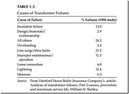
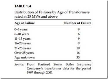
Table 1.3 displays results of Harford Steam Boiler Insurance Company (HSB) 1998 study on the causes of transformer failures. Table 1.4 displays the results of HSB 2003 study on distribution of transformer failures. For the causes of failures reported line surge/through faults are the number one cause for all types of failures. Insulation failure was the second leading cause of trans- former failures and these failures were attributed to defective installation,
insulation deterioration, and short circuits. For failures due to aging, the winding insulation looses mechanical and dielectric withstand strength over time and therefore is weakened to the point where it can no longer sustain the high radial and compressive forces induced by a line surge, or an internal or through fault. Also, as the load increases due to system expansion, the operat- ing stresses increase in a transformer.
Large power transformers used in the medium-voltage electrical distribu- tion system are typically of liquid-immersed type. The primary and secondary coils are immersed in oil, which acts to insulate as well as cool the coils. The coils are wrapped on an iron core, which is enclosed in a tank and filled with oil. A dedicated cooling system consisting of finned radiators with temperature-controlled cooling fans will be provided to remove heat from the internals. In addition, some cooling systems include one or more circulating pumps to increase the flow of oil through the heat exchanger and provide more efficient core cooling. The insulating oil is circulated through the trans- former tank and heat is rejected via the heat exchanger. The power for the circulating pumps and cooling fans is typically 480 V AC. Smaller power transformers, such as those found in load center switchgear, may be either oil- filled or dry-type units. Dry-type transformers may be air-cooled with natural circulation alone, or more typically, forced-air-cooled with temperature- controlled cooling fans. Power connections to electrical buses and cables are routed through insulated bushings to the interior transformer windings.
Age-related degradation of transformers is primarily associated with the coils and the electrical connections. Degradation of the coils can occur due to continual exposure to elevated temperature, or degradation of the insulating oil. When the oil starts to degrade, gas is generated, which will accumulate inside the transformer tank. Checking for gas content in the oil is one method of transformer condition monitoring. Moisture intrusion is also a concern since entrained moisture can cause the formation of bubbles in the insulat- ing oil during transformer operation. Formation of bubbles can degrade the performance of the transformer. Some examples of failure causes of power transformers are the following:
• Short circuit to ground
• Turn-to-turn short
• Primary to secondary short
• External oil leakage
• Degraded or inoperable cooling system (reduces transformer million volt amperes (MVA) rating)
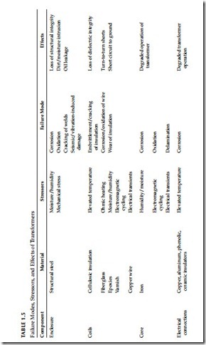
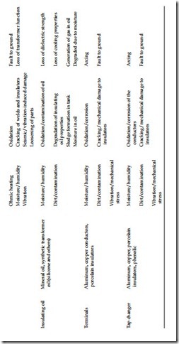
To develop and implement a rigorous PM program, an understanding of trans- former failure modes is necessary. The transformers can fail from any combi- nation of electrical, mechanical, and thermal factors. Actual transformer failures as listed above involve breakdown of the insulation system which may result from any of the factors (failure modes) just mentioned above. Table 1.5 summarizes the stressors, failure modes and effects of power transformers.
Electrically induced failures: These involve transient or sustained overvoltage conditions, lightning and switching surges, partial discharges, and static electrification. The partial discharges may be caused by poor insulation system design, by manufacturing defects or by contamination of the insula- tion system (both oil and solid insulation).
Mechanically induced failures: A mechanically induced failure is due to deform- ing of a transformer’s windings that eventually results in the abrasion or rupturing of its paper insulation. Transformer winding deformation happens in either during shipping or during magnetically induced electromechanical forces. When a transformer experiences an internal or heavy through fault, the windings are subjected to electromechanical forces that are beyond their design capability. When this happens, it can cause hoop (inward radial) buckling of the innermost windings, conductor tipping, conductor telescoping, spiral tightening, end ring crushing, and/or failure of the coil clamping system.
Thermally induced failures: Thermal degradation causes the paper insulation of the windings to loose its physical strength to the point where it can no longer withstand the vibration and mechanical movement that occur inside a transformer. The thermally induced failures are due to overloading beyond its design capability for long period of time, failure of the cooling system to dissipate heat, blockage of axial oil duct spaces, operating the transformer in an overexcited condition, and/or excessive ambient temperature conditions. Refer to Section 5.7.3.7 for more details on causes of transformer failures.
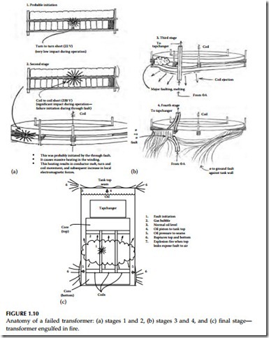
An anatomy of a transformer failure is illustrated in Figure 1.10 based on a root cause analysis of a station service transformer that failed in service cata- strophically. The transformer was about 7 years old when it failed as a result of through fault because it had an incipient turn-to-turn fault in one of the phase winding. Because of lack of preventive and/or predictive maintenance testing over the 7 years, the fault went undetected until one day the transformer failed with dire consequences. As illustrated in Figure 1.10a, the original fault was a minor fault and was inconsequential to normal operation of the transformer. However, as the current dramatically increased under a through fault condi- tion, the minor fault developed into a major fault (Figure 1.10b and c).
Switchgear and Circuit Breakers
The insulating materials used for bus bar insulation and mechanical support in switchgear and circuit breakers are ceramics, epoxy resins, epoxy resin bonded glass fiber, polyester resins, vulcanized fiber, and synthetic resins bonded paper. In low-voltage breakers, synthetic resin moldings are used as insulating materials for the metallic parts. The modern practice is to use thermosetting plastics for bus bar mounting in switchgear to better withstand electromechanical and electrodynamic forces arising out of system faults. The thermosetting compounds are known as dough molding compounds (DMCs) and sheet molding compounds (SMCs). These compounds are basically made up of fiber- or glass-reinforced thermosetting plastics that
posses good physical and thermal stability, high mechanical strength, and excellent electrical properties. These compounds have essentially replaced the older insulating materials such as bakelite (phenol formaldehyde) and veneered impregnated wood used in switchgear applications.
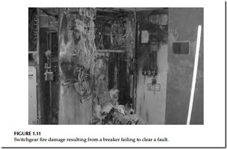
The SF6 gas, air, vacuum, and oil are used as arc-quenching medium in circuit breakers. The mechanisms vary depending on voltage rating, the type, and vintage of circuit breakers. For breakers, the reliability concerns extend to not only insulation but also to the correct functioning of the operating mechanism, protective devices, and control that are integral to the breaker. Unlike transformers that are a quiescent element, switchgear breakers are active elements that can fail by acting spuriously or by not functioning (either to open or close) upon command. These incorrect functions can create problems in the connected circuits that are quite different from those that result directly from any fire, explosion, or spread of possibly toxic insulating fluids. If a breaker fails to clear upon signal or becomes overloaded for any reason, then the circuit will be subjected to further damage until an upstream breaker (usually larger and set at a higher current rating) can sense and clear the overload. If, on the other hand, a breaker fails to close, this normally means that all circuits that receive power from this feed point cannot perform their intended functions. Fortunately, most breakers are located in enclosed segregated areas, which provide containment and fire protection capabilities, as well as in their own cabinets, which help limit any physical damage to immediately adjacent equipment. However, switchgear fires can be catastrophic and incidents have occurred where complete line up of switchgear has burned down due to breaker failing to clear a fault. An exam- ple of switchgear burndown is shown in Figure 1.11.
Circuit breakers in the medium-voltage electrical system are typically of the metal-clad type, and are commonly part of a switchgear assembly. The switchgear assembly comprises of the following:
• Circuit breakers
• Bus bars
• Relays and control power
The circuit breakers are constructed of a number of different mechanical and electrical subsystems, all of which are contained in a metal enclosure. Typically, switchgear and circuit breakers are located in a mild environment such as a switchgear room therefore, they would not be exposed to harsh environment. However, space heaters are always installed in circuit breaker cubicles to pre- vent moisture and condensation when it is not carrying load. The predominant stressors are expected to be operational stressors, such as mechanical wear of the moving parts and electrical cycling, as well as exposure to contaminants such as dust and dirt. Operation of the circuit breakers requires a number of mechanical, as well as electrical systems. Mechanical linkages, together with springs and latches are used to open and close the breaker. Repeated operation of the breaker can lead to wear of these components over time. Electrical tran- sients can generate substantial electromagnetic forces that act on circuit breaker components and supports. Powerful vibrations are produced when a circuit breaker mechanism opens to interrupt an electrical arc. This can result in misalignment, bending, twisting, binding, or even breakage of the various mechanical components resulting in degraded performance or loss of function. Electrical cycling of the power path in the breaker can also lead to degrada- tion of the various electrical components, such as the contacts and arc extin- guishing components. When the contacts arc during breaker operation, small amounts of metal are vaporized and deposited on the arc chutes. As these deposits build up over time, they can increase the conductivity of the chutes and diminish their ability to extinguish the arcs. Another electrical system that can lead to breaker failure is the control power system. Typically, 125 V DC control power is used for a line up of switchgear breakers for tripping, closing, and to operate the peripheral equipment such as the spring charging motor. The closing and peripheral control power circuit normally includes a fuse. Degradation of this circuit, as well as the fuse and fuse holder can lead to loss of control power to the breaker and, thus, loss of breaker function. Failure modes for medium-voltage circuit breakers are the following:
• Failure to close
• Failure to open
• Spurious opening
• Spurious closure
• Failure to operate as required
• Failure to recharge closing spring
• Slow operation
• Short circuit to ground
• Out of calibration
• Intermittent operation
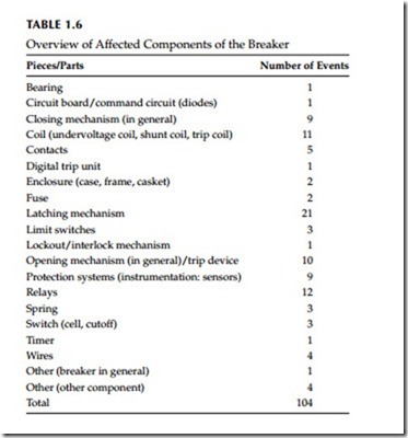
In a recent study of medium- and low-voltage circuit breakers used in nuclear power plants world wide, 104 events were identified with respect to failure
modes as shown in Table 1.6. The following failure symptom categories were identified as being important:
• Movement of the breaker mechanism is impeded by insufficient or inadequate lubrication
• Movement of the breaker mechanism is impeded by broken, bent, or loose parts, friction, binding, resulting from excessive stress, wear, or faulty installation
• Operation of the breaker is impeded by incorrect adjustment of set points/limit switches
• Various electrical problems caused, e.g., by defective coils, defective command circuits, wiring faults, loose wires, poor contacts, and blown fuses
• Others (e.g., dirt, pollution, and corrosion)
As result of this investigation two principal categories of failure causes were identified. They are
Deficiencies in operation: This group comprises all events that involve human errors, expressed by a human error related root cause.
Three failure cause categories were identified as being important in this group:
• Deficient procedures for maintenance and/or testing
• Insufficient attention to aging of piece parts
• Operator performance error during maintenance/test activities
Deficiencies in design, construction, and manufacturing: This group comprises all events with hardware related root causes. Two failure cause categories were defined for this group as being important:
• Deficiency in design of hardware
• Deficiency in construction or manufacturing of hardware
Many breakers sit in open or closed position for long periods of time without having to change their state. Therefore, it is difficult to assess whether a breaker is trouble free and will respond correctly when called upon to perform its intended function. It is imperative that a clear understanding exists on how and what fails within a circuit breaker. Once the failure modes are identified then a method can be developed that can detect these failures modes before an actual failure occurs. The level of monitoring (maintenance and testing) for a particular type of circuit breaker is dependent on the circuit breaker age, type, application, and the risks associated with the loss of function of the circuit breaker including its associated power or protection and control support com- ponents (Table 1.7). The circuit breaker failure modes are discussed as follows:
Insufficient or inadequate lubrication: Movement of the breaker mechanism is impeded by lack of lubrication, more than half of them affecting the latching mechanism. This suggests that improvements in the maintenance practices should be concentrated upon checking the status of lubrication more regularly.
Mechanical wear: Movement of the breaker mechanism is impeded by wear, broken, bent, or loose parts, friction, binding, resulting from excessive stress, or faulty installation. Mechanical wear is the dominant failure mechanism in this failure symptom/manifestation category. Wear mostly affected the latching mechanism, coils, and relays. Besides deficient maintenance/test procedures and practices, insufficient awareness of aging of breaker piece parts also contributes significantly to this category.
Various electrical problems: This failure cause could be defective coils and command circuits, wiring faults, loose wires, blown fuses, and poor con- tacts. Defective coils and defective command circuits are the dominant failure mechanisms in this category. The events are mostly caused by deficiencies in design, construction, and manufacturing.
