Principal Technical Issues in Grid Interconnection
The purpose of outlining the requirements of a generic grid code is to provide a suggestion of the technical specifications, which should be satisfied by a generic RPP when connected to the system [23]. The technical terms of grid codes are divided into two major classes—static and dynamic requirements. Among these two classes, the static part of each code consists of issues related to continuous operation of generation units. Voltage and reactive power control, power factor requirements, frequency requirements, and power quality are some of the common issues, which are addressed. The dynamic part of the codes considers issues regarding the operation of RPPs during fault sequences and disturbances in the grid.
Static Regulations
The first part of the grid code focuses on the static requirements. A few of these requirements contain time limits or operate within fixed time frames. The values are, however, still constant within the mentioned time frames and hence semi- static regulations are included in this static analysis. Normally, these requirements are specified at the point of common coupling (PCC) of the RPPs [23].
Reactive Power and Voltage Regulation
Voltage regulation in a power system is dependent on flow of reactive power as well as on short circuit capacity and impedance of the network. By operating in a wide range of power factors, conventional generation units have traditionally provided reactive power to support system voltage. Voltage regulators on their excitation systems provide the primary voltage control function. However, lack of this capability leads to problems such as depressed voltages and excessive voltage fluctuations, which have been found common with many old wind turbines. Another important parameter that influences voltage at PCC is tap-changing operation of on-load tap changer transformers. The speed of response of the tap changer, the size of the first step, and those of subsequent steps are all relevant parameters that influence the voltage at PCC of RPP [24].
In general, there are three common reactive power control modes for RPPs [8]:
(a) Fixed reactive power mode: As specified by TSO/regulator, reactive power flow at certain set point is maintained.
(b) Fixed power factor mode: In this mode, the ratio between active and reactive power is maintained. This mode is common for small-scale generators connected at the distribution level.
(c) Voltage set-point control mode: Necessary reactive power is injected at PCC to regulate the voltage magnitude.
The reactive power generation capability of the RPPs at PCC is defined by power factor regulation. With the development of converter technology, the doubly fed induction generator (DFIG) wind turbines have come up with both capacitive and inductive reactive power capabilities according to active power output. With increased rating of the grid side converter, full-converter based variable speed wind turbines offer even wider range of reactive power capability compared to DFIG turbines [25]. By using additional Static Var Compensator (SVC), STATic COMpensator (STATCOM), and other reactive support equip- ment at the plant level, reactive power capability of wind and solar plants can be further enhanced.
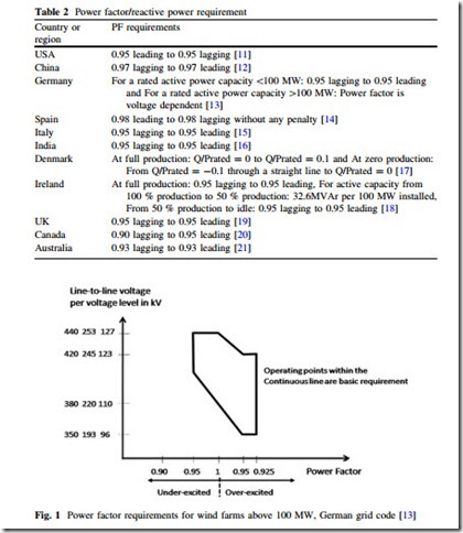
Power factor requirements and reactive power capabilities are more or less similar in the reviewed grid codes. Table 2 illustrates these requirements.
Power factor requirements in countries such as USA, China, Denmark, and Australia are relatively simple. The RPPs are requested to operate within the range specified by capacitive and inductive power factor. For example, in Australia WPPs must be able to continuously operate at their rated output power within the range of 0.93 capacitive to 0.93 inductive power factor [21]. However, this set of requirements is applicable only to Automatic Access Standard formulated by AEMC. The minimum access standard does not allow supply or absorption of reactive power at PCC. Some grid codes consider the variation in voltage level while fixing power factor/reactive power requirements at PCC. German grid code for WPPs is one such example [13].
In Germany, the reactive power requirements for WPPs consist of two parts.
WPPs with ratings less than 100 MW have similar reactive power requirement as in other grid codes. These WPPs need to be operated within the range of 0.95 capacitive to 0.95 inductive power factor. However, reactive power requirement for the WPPs with ratings over 100 MW is voltage dependent [13].
Figure 1 illustrates the reactive power requirements of each turbine in WPPs over 100 MW in size. The power factor range changes from 0.925 capacitive–0.95 capacitive at minimum operating voltage to 0.95 inductive–0.925 capacitive at the
full power factor operation. The power factor requirement is from inductive 0.95–1.0 at the maximum operating voltage [13].
In Spain, the WPP with reactive power capability is paid an additional bonus, whereas a lack of reactive power to maintain the mentioned power factor at PCC results in a penalty. Bonus or penalty is calculated as a percentage of a reference tariff expressed in €/MWh [26].
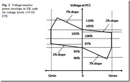
In Canada, the reactive power requirements for WPPs are specified under continuous as well as dynamic operating conditions. WPPs need to be operated within the power factor range of 0.9 capacitive to 0.95 inductive under steady state. For dynamic conditions, power factor ranges from 0.95 capacitive to 0.985 inductive. The Canadian grid code also demands WPPs to be incorporated with voltage set-point control mode [27]. With a step change in the voltage set-point, the voltage control loop should be adjusted to attain 95 % of the reference reactive power within 0.1–1 s [20]. Besides the Canadian grid code, wind plants in the UK connected to a line rated 33 kV or above are required to contribute to voltage control with a predefined reactive power–voltage droop characteristic as shown in Fig. 2. In case of an unexpected voltage variation in grid, the WPP is required to start reacting within 200 ms and should provide at least 90 % of the required reactive power within 1 s. After 2 s from the event, the fluctuations in the reactive power output should be limited within ± 5 % of the target value [19].
Continuous Voltage Operating Range
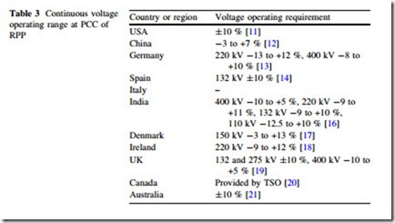
Table 3 illustrates the continuous voltage operating requirements for RPPs in reviewed grid codes. The RPPs are asked to operate within the continuous operating voltage range as mentioned in Table 3. At specified continuous operation range, the voltages inside the RPPs must be within the tolerable voltage range of their constituent components.
Frequency Operating Requirement
System events that embrace load-generation mismatches often result in transient fluctuations of system frequency. Mechanical failures of generators, abrupt load changes, or loss of line in the transmission system are a few of the reasons behind such anomalies. The rate and depth of frequency fluctuations and the time for the frequency to return to its pre-event nominal value are affected by the dynamics of the generation mix.
In the presence of a large share of RPP such as WPP, this load-generation mismatch issue is obvious during simultaneous light load and high wind periods. Due to economic consideration, fewer synchronous generators will be operating, which would consequently reduce the overall grid inertia.
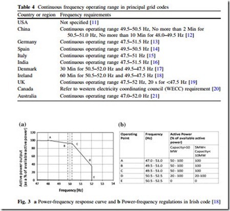
Table 4 shows the frequency operating requirements for RPPs in the reviewed codes.
In general, the TSOs request the generators’ primary frequency control to maintain the continuous frequency limit at PCC. Some TSOs require wind plants to be equipped with an inertia emulation system to support system frequency following a major frequency event [28]. The design considerations for inertial response emulation include: (a) the optimal amount of power that can be drawn from the rotating masses; (b) the duration of the momentary injection; and (c) the duration of the speed and energy recovery phase. Several frequency control techniques reported in research and in practice can be found in [29–32].
Almost all the grid codes state that some power ramp rate limitation or active power curtailment should be used to control frequency deviation at the wind farm level. The Irish grid and the connected WPPs can be taken as a good example for this control. Due to weak interconnection with the neighboring systems, the Irish grid faces notorious frequency variation on a regular basis. Therefore, the Irish
grid code demands WPPs to control active power as close to real-time as possible according to the response curve described in Fig. 3. The rate of response should be 1 % of rated power per second for each online wind turbine generator (WTG) [18]. Other European grid codes also contain similar requirements [8].
Power Quality
The power system needs to run in a stable state and be able to deliver power to consumers at an acceptable quality. Harmonics and flicker at PCC are two major power quality disturbances, which need to be taken care of while harnessing power through RPPs. Sources, which contributes in harmonics injection in RPP include [33]:
(a) Generator technology—Wind turbines utilizing static power converters and modern power converters used in bulk PV applications inject harmonics.
(b) Dynamic reactive power compensation equipment—SVCs and STATCOMs also inject harmonics into the grid.
(c) Collector system feeders—In offshore WPPs, long AC submarine cables set off critical resonances with the power system at relatively low frequencies.
(d) Electric grid itself—The impedance of grid is a function of loading level and switching state in the grid. The worst case network impedance needs to be assumed while determining the contribution of WPP to the harmonic voltage distortion at PCC [8].
In the United States and Canada, the IEEE Standard 519 [34] sets out the quality of power that an electric utility is expected to deliver to the customer at PCC. Section 5 of Chapter ‘‘HVDC Transmission for Offshore Wind Farms’’ of IEEE Standard 519 recommends that as a percentage of the nominal fundamental frequency voltage in the utility service, the voltage distortion limits should not exceed 5 % for the total harmonic distortion (THD), and 3 % for any individual harmonic. The Danish grid code sets a more stringent rule where it demands THD to be less than 1.5 % and distortion factor (DF) for an individual harmonic to be less than 1 %. Engineering Recommendation G5/4 defines the harmonic requirements in UK and Scotland. Summary of UK THD limits at planning level are given in Table 5. Details of allowable harmonic voltages at various levels can be found in [35].
Flicker is fluctuation in the system voltage and it can produce noticeable changes in light output. In many cases, flicker becomes annoying and objection- able. Step changes in transmission system voltage can occur due to switching in and out of lines, cables, capacitors, transformers, and other generating plant. In a solar plant, abrupt change in the irradiance and power output of the facility occurs due to passing clouds. This results in noticeable flicker. Variations in WTG power output due to variation in wind speed, tower shadowing, wind shear or gradient, blade pitching, and WTG start and stop operations are few reasons, which cause flicker in a wind farm [36]. Flicker is only a concern for distribution interconnections in areas of the system where fault currents are very low, i.e., in weak systems [10].
IEEE Standard 1453 [37] has primarily adopted IEC 61000-4-15 [38] to provide uniformity to international standards. Short-term flicker (Pst) is measured as a weighted average of the flicker contribution over 10 min, whereas long-term flicker value (Plt) is measured as a weighted average of the flicker contribution
over 2 h [23]. The recommended values of Pst and Plt at planning levels are given in Table 6.
According to the Danish grid codes Pst and Plt values should be limited to 0.30–0.20, respectively. Among European grid codes, it is primarily the Danish code, which mentions restrictive regulations regarding flicker. The German and Irish codes do not mention anything on flicker [25].
Dynamic Regulations During and After Disturbances
Reliability of the interconnected power system is greatly affected by system disturbances. System disturbances include asymmetrical or symmetrical faults on transmission system elements. Dynamic regulations also consider associated switching to clear the faulted elements and other system elements. It is expected that transition to the acceptable, new steady state is stable and fast enough after such disturbances. Along with control and protection units, generation units play a significant role in providing satisfactory dynamic performance [6].
Low Voltage Ride Through
Unless the conventional synchronous generators are physically disconnected from the system due to disturbance, they can be defined as riding through [6]. When a fault occurs in an electric network, the supply voltage drops to a lower level until the protection devices detect the faulty region and isolate it from the rest of the network [3]. Depending on the type and location of the fault, RPPs experience a voltage sag condition at PCC and consequently get disconnected from the grid. The disconnection of RPPs under such voltage anomalies is not acceptable when renewable energy constitutes a large share of the total generation. Thus, modern grid codes demand large RPPs to continue their uninterrupted operation according to given voltage–time profiles under different fault conditions. Specifications related to undervoltage are usually identified as low voltage ride-through (LVRT).
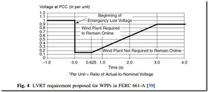
Figure 4 shows LVRT requirement according to FERC Order 661-A as an example. The curve in Fig. 4 represents a boundary within which voltage at PCC is expected to be held. That means a WPP shall remain connected to the transmission
system under the fault conditions when the voltage measured at PCC remains above the solid line for any fault in the network [39].
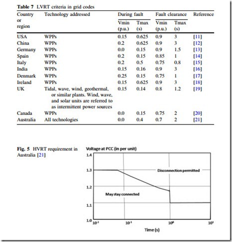
LVRT capability curves proposed in international grid codes are somewhat similar to Fig. 4. However, quantitative features of those curves may vary from one TSO/regulator to another. Table 7 lists the important parameters of LVRT requirements in the principal grid codes considered in the present study.
The German grid code has no regulations for asymmetrical voltage sags, but demands ride-through capability for three-phase faults with the PCC voltage drop to zero for the maximum duration of 150 ms, followed by voltage recovery to 0.8 p.u. within 1.5 s. In USA, the older version of German LVRT curve has been adopted by FERC. Minimum voltage for this curve is 0.15 p.u for 0.625 s and the voltage recovery period is set at 3 s [11]. Similar requirements can be observed with EirGrid in Ireland [18]. The Spanish grid code requires WPPs to endure three-phase faults with PCC voltage down to 0.2 p.u. for 0.15 s, followed by the voltage recovery to
0.85 p.u. during the next 1 s. On the other hand, for two-phase faults, continuous operation of WPPs is requested at 0.6 p.u. for the maximum duration of 0.5 s [14]. The Indian grid code has varying fault clearing times with different nominal volt- ages at PCC. At 400 kV, fault clearing time is set at 100 ms, whereas at 220 and 66 kV the clearing times are set at 160 and 300 ms, respectively [16]. In Australian code, WPPs must remain connected for symmetrical as well as for asymmetrical faults with the voltage drop to 0 p.u. for 140 and 400 ms, respectively. The supply voltage has got to return to 0.7 p.u. in 2 s and 0.8 p.u. in 10 s [21].
High Voltage Ride Through
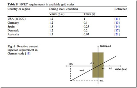
Voltage swell conditions at PCC can occur due to switching off large loads, energizing capacitor banks, or faults in the grid [40]. In order to ride through such a condition, a requirement known as high voltage ride through (HVRT) has been recently added in the grid codes of Germany, Spain, Denmark, and Australia. In USA, WECC sets high voltage boundary for all kinds of RPPs [41]. Figure 5
shows the HVRT requirement according to the Australian grid code. Table 8 lists the HVRT requirements for other grid codes in quantitative form. It is obvious that the Australian and Spanish grid codes have the most challenging HVRT regulations that insist WPPs to withstand voltage swell of 1.3 p.u [14, 21].
Reactive Current Injection During Fault
Along with LVRT and HVRT capability curves, a few grid codes demand reactive current support at PCC during the fault period and/or fast active power recovery after the clearing of a fault. These rules are enforced by TSOs/regulators to utilize
the control potential of new WPPs to support stability during and after system faults. Grid codes of Germany, Spain, UK, and Australia define such regulations on the reactive power response during faults. The Australian grid code demands that if the voltage at PCC drops below 90 %, WPPs must provide capacitive reactive current of at least 4 % of their maximum continuous current for each 1 % reduction in the PCC voltage [21]. Figure 6 shows the reactive current injection rule in the German grid code, which has a similar regulation to the Australian code. However, in the German code, WPP requires the injection of 2 % reactive current for each percent reduction in the PCC voltage [13]. The British and Spanish codes state that WPPs must produce their maximum reactive current during a voltage dip at PCC due to grid fault [14, 19]. Some grid codes also specify the active power recovery time after the fault. The active power recovery requirement in the Irish grid code is stated as-‘‘WTG must be able to provide at least 90 % of its maximum active power within 1 s of the system voltage recovering to the normal operating range’’ [18].
Repetition of Faults
A distinctive disturbance attribute has been included in the Danish grid code where TSO demands WPPs in operation irrespective of quick repetition of faults. Generally such repetition is the result of unsuccessful line reclosing [6, 17]. According to that code, a wind turbine generation unit must have sufficient capacity to meet the above mentioned requirements. According to the Danish code, the WPP must have the capacity to withstand the following three independent sequences [23]:
(a) Minimum two single-phase ground faults within 2 min;
(b) Minimum two two-phase short circuits within 2 min;
(c) Minimum three-phase short circuits within 2 min.
