Drive power circuits
The control of a dc motor is based upon the precise control of the voltage or current supplied to the armature and field windings. AC motor control is based upon the
precise control of the supply in terms of frequency, the magnitude of the voltage and, in some cases, the phase angle of the supply in relation to rotor position.
A large number of power semiconductor-based converter circuits exist to form voltage or current sources. The principles of many of these circuits are reviewed in Chapter 11 and only the most important practical types of circuit for motor drives are discussed in the following sections.
DC motor drive systems
In section 10.2 it is shown that complete control of a dc machine can be achieved by controlling the armature voltage Va and the field current If. Two power converters are employed for this purpose in most variable speed drives which employ the separately excited dc machine. (In referring to the number of converters in a drive, it is common to ignore the field converter; this nomenclature will be adopted here). It is relatively common in simple drives for the field converter to be a single-phase uncontrolled bridge thereby applying fixed field voltage.
Where the variation in motor resistance with temperature, or a poorly regulated supply, results in unacceptable variations in field current, a controlled power converter is employed with current control. Such field controllers are further discussed later as applied to field-weakening control.
AC to dc power conversion
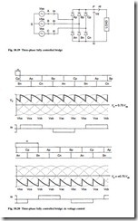
The three-phase fully controlled converter dominates all but the lowest powers where single-phase converters are used and Fig. 10.19 shows the power circuit together with associated ac/dc relationships. Figure 10.20 shows how the dc voltage can be varied by adjusting the firing delay angle α. The pulse number p, of this bridge is 6 and energy flow can be from ac to dc or dc to ac.
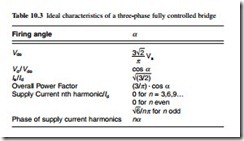
The salient ‘ideal’ characteristics of the three-phase fully controlled bridge are shown in Table 10.3.
The above characteristics are based upon idealized conditions of negligible ac inductance and constant dc current, but these are not often found in practice. It is not possible to consider all practical effects here, but the effect of dc link current ripple on
ac supply harmonics is of great practical industrial importance mainly in relation to three-phase bridges. Practical experience has led to the adoption by many of I5 = 0.25I1 (the ideal being 0.2I1), I7 = 0.13I1 (the ideal being 0.14I1), I11 = 0.09I1 (the ideal being 0.11I1) and I13 = 0.07I1 (the ideal being 0.08I1). In general, the amplitudes of higher harmonics are rarely of significance with regard to supply distortion. Under conditions of very high dc current ripple, the 5th harmonic can assume a considerably higher value than that quoted here. A practical example would be an application with a very capacitive dc load such as a voltage source inverter; in such a case where no smoothing choke is used, I5 could be as high as 0.5I1.
Single-converter drives
Figure 10.21 shows a single-converter dc drive. In its most basic form the motor will drive the load in one direction only without braking or reverse running. It is said to be a single-quadrant drive, only operating in one quadrant of the torque–speed characteristic. Such drives have wide application from simple machine tools to fans, pumps, extruders, agitators and printing machines.
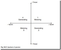
For full four-quadrant operation, a drive is required to operate in both the forward and reverse directions and to provide regenerative braking. This is illustrated in Fig. 10.22. A single fully controlled converter can still be used but some means of reversing, either the field or armature connections, as shown in Fig. 10.23, must be added.
Reversal of the armature current can involve bulky (high current) reversing switches, but due to the low inductance of the armature circuit it can be completed in
typically 0.2 seconds. Field current reversal takes longer, typically in the order of 1 second, but lower cost reversing switches may be used. The field reversal time can be reduced by using higher voltage field converters to force the current. Forcing voltages up to 4 per unit are used but care must be taken not to over-stress the machine. This increased voltage cannot be applied continuously and either a switched ac supply or a controlled field converter is required. Armature and field reversal techniques are used where torque reversals are infrequent such as hoists, presses, lathes and centrifuges.
Dual-converter drives
When a four-quadrant drive is required to change the direction of torque rapidly, the delays associated with reversing switches described earlier may be unacceptable and a dual converter comprising two fully controlled power converters connected in
inverse-parallel can be used as shown in Fig. 10.24. Bridge 1 conducts when the armature current Ia is required to be positive and bridge 2 when it is required to be negative.
There are two common forms of dual converter. In the first, both bridges are controlled simultaneously to give the same mean output voltage. The instantaneous voltages from the rectifying and inverting bridges cannot be identical, and reactors Lp are included to limit the current circulating between them. The principal advantage of this system is that when the motor torque, and hence current, is required to change direction, there need be no delay between the conduction of one bridge and the other. This is the dual converter bridge with circulating current.
In the second, the circulating current-free dual converter, only one bridge at a time is allowed to conduct. The cost and losses associated with the Lp reactors can then be eliminated, and economies can also be made in the drive control circuits. The penalty is a time delay of typically 10 ms as the current passes through zero, while it is ensured that the thyristors in one bridge have safely turned off before those in the second are fired. This circulating current-free dual converter is the most common industrial four-quadrant drive and is used in many demanding applications. Paper, plastics and textile machines where rapid control of tension is required are good examples.
Field control
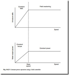
By weakening the field as speed increases, a constant power characteristic can be achieved. The field can be controlled by a three-phase (or often a single-phase) fully controlled bridge. By including this converter in a speed-control loop, it can be arranged that as speed increases, the armature voltage rises to the point where it matches the pre-set reference in the field controller. Above that speed, an error signal is produced by the voltage loop, which causes the field controller to weaken the motor field current and thereby restore armature voltage to the set-point level. The resulting characteristics are shown in Fig. 10.25.
DC to dc power conversion
The principles of dc to dc power converters are explained in section 11.4.1. They pro- vide the means to change one dc voltage to another; step-up (or boost) converters are available and have potential for the future, but step-down (or buck) converters are of greatest commercial interest and will be concentrated upon here. These converters are usually supplied from an uncontrolled ac to dc converter or a battery supply; their output can be used to control a dc machine as in the case of the controlled ac to dc converters.
Several important limitations of ac to dc converters are overcome by the dc–dc converter, as follows:
● the dc ripple frequency is determined by the ac and is, for a 50 Hz supply frequency, 100 Hz for single-phase and 300 Hz for three-phase fully controlled bridges. This means that additional smoothing components are often required when using high speed machines, permanent magnet motors or other special motors with low armature inductance.
● as a result of the delay inherent in thyristor switching (3.3 ms in a 50 Hz three- phase converter) the current control loop band width of the converter is limited to approximately 100 Hz, which is too low for many servo drive applications.
● thyristor controlled ac to dc converters have an inherently poor input power factor at low output voltages. The near-unity power factor can be achieved using an uncontrolled rectifier feeding a dc to dc converter.
● electronic short-circuit protection is not economically possible with thyristor converters. Protection is normally accomplished by fuses.
DC to dc converters are more complex and less efficient than ac–dc converters, but they find application mainly in dc servo drives, rail traction drives and small fractional drives employing permanent magnet motors. In the examples which follow, the circuits are illustrated showing bipolar transistors, but MOSFETs, IGBTs and, at higher powers, GTOs are widely used.
(a) Single-quadrant step-down dc to dc converter
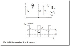
The most basic dc to dc converter is shown in Fig. 10.26. The output voltage is changed by pulse-width modulation (PWM), that is, by varying the time for which the transistor T is turned on and the voltage applied to the motor is therefore in the form of a square wave of varying period. The principle of PWM is explained in section 11.4.4. Because the motor is inductive the current waveform is smoothed, the flywheel diode D carrying the current whilst the transistor is turned off. The basic formulae relating the variables in Fig. 10.26 are as given in eqns 10.12 and 10.13.
where f is the frequency of transistor ‘on pulse’ (Hz), DIa is the maximum deviation of armature current and t is the on-pulse duration.
Applications for this circuit are normally limited to drives below 5 kW and simple variable speed applications.
(b) Four-quadrant dc to dc converter (the H-bridge)
Figure 10.27 shows a basic four-quadrant converter. During motoring, positive output transistors T1 and T4 are switched on during the on-period, whilst diodes D2 and D4 conduct during the off-period. When D2 and D4 conduct, the motor supply is reversed and consequently the voltage is reduced to zero at 50 per cent duty cycle. Any reduction of duty cycle below 50 per cent will cause the output voltage to reverse but with current in the same direction; hence the speed is reversed and the drive is regenerating.
With transistors T2 and T3 conducting, the current is reversed and hence the full four-quadrant operation is obtained. These converters are widely used in high- performance dc drives such as servos.
AC motor drive systems
AC to ac power converters with intermediate dc link
This category of ac drive commonly termed the variable frequency inverter is by far the most important in respect of the majority of industrial applications. It is considered here as a complete converter, although the input stages have been considered earlier in isolation, and their individual characteristics are, of course, applicable. Alternative input stages to some of the drives are also applicable.
The concept of these inverter drives is well understood, being rectification of fixed frequency, smoothing and then inverting to give variable frequency, variable voltage to supply an ac machine. Within this broad concept two major categories exist. First, in the Voltage Source Inverter, the converter impresses a voltage on the motor, and the impedance of the machine determines the current. Secondly, in the Current Source Inverter, the converter impresses a current on the motor, and the impedance of the machine determines the voltage. For most industrial applications the PWM voltage source inverter is applied, and only this converter will be considered here.
General characteristics of a voltage source inverter
Voltage source inverters can be considered as a voltage source behind an impedance, and consequently they are very flexible in their application. Major inherent features include the following:
● multi-motor loads can be supplied. This can be very economical in applications such as roller table drives and spinning machines.
● inverter operation is not dependent upon the motor characteristics. Various machines (induction, synchronous or even reluctance) can be used, provided the current drawn is within the current rating of the inverter although care should be taken where a low power factor motor is used to ensure that the inverter can provide the required reactive power.
● open-circuit protection is inherent. This is useful in applications where the cables between the inverter and the motor are insecure or subject to damage etc.
● the facility to ride through mains dips can easily be provided by buffering the dc voltage link with capacitance or, where necessary, a battery.
● motoring operation only in both directions is possible without the addition of resistive dumps for braking energy or expensive regenerative converters to feed energy back to the supply.
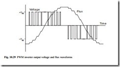
In the PWM inverter drive shown in Fig. 10.28, the dc link voltage is uncontrolled and derived from a simple diode bridge. The output voltage can be controlled electronically within the inverter by use of the PWM techniques explained in section 11.4.4. In this method, the transistors are switched on and off many times within a half cycle to generate a variable voltage output which is normally low in harmonic content. A PWM waveform is illustrated in Fig. 10.29.
A large number of PWM techniques exist, each having different performance notably in respect to the stability and audible noise of the driven motor. The use of PWM virtually eliminates low-speed torque pulsations since negligible low-order harmonics are present so this is an ideal solution where a drive system is to be used across a wide speed range.
Since voltage and frequency are both controlled with the PWM, quick response to changes in demand can be achieved. Furthermore, with a diode rectifier as the input circuit a high power factor, approaching unity, is offered to the incoming ac supply over the entire speed and load range.
The PWM inverter drive efficiency typically approaches 98 per cent but this figure is heavily affected by the choice of switching frequency, the losses being greater where a higher switching frequency is used. In practice the maximum fundamental output frequency is usually restricted to about 1 kHz for a transistor-based system. The upper frequency limit may be improved by making a transition to a less sophisticated PWM waveform with a lower switching frequency and ultimately to a square wave if the application demands it. However, with the introduction of faster switching power semiconductors, these restrictions to switching frequency and minimum pulse-width have been eased.

