Introduction
Uninterruptible power systems have become a virtual necessity for powering large or small computer systems where the application serves a critical need. Computers and data communications systems are no more reliable than the power from which they operate. The difference between UPS and emergency standby power is that the UPS is always in operation. It reverts to an alternative power source, such as the utility company, only if the UPS fails or needs to be deactivated for maintenance. Even then, the transfer of power occurs so quickly (within milliseconds) that it does not interrupt proper operation of the load.
Emergency standby power is normally off and does not start (manually or automatically) until the utility ac feed fails. A diesel generator can be started within 10 to 30 s if the system has been maintained prop- erly. Such an interruption, however, is far too long for DP hardware. Most DP systems cannot ride through more than 8 to 22 ms of power interruption. Systems that can successfully ride through short-duration power breaks, as far as energy continuity is concerned, still may enter a fault condition because of electrical noise created by the disturbance.
UPS hardware is available in a number of different configurations. All systems, however, are variations of two basic designs:
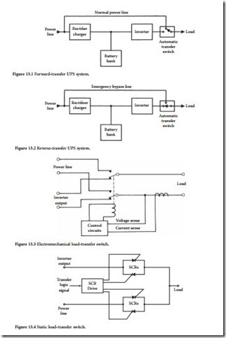
• Forward-transfer mode: The load normally is powered by the utility power line, and the inverter is idle. If a commercial power failure occurs, the inverter is started and the load is switched. This configuration is illustrated in Figure 13.1. The primary drawback of this approach is the lack of load protection from power-line disturbances during normal (utility-powered) operation.
• Reverse-transfer mode: The load normally is powered by the inverter. In the event of an inverter failure, the load is switched directly to the utility line. This configuration is illustrated in Figure 13.2. The reverse-transfer mode is, by far, the most popular type of UPS system in use for large-scale systems.
The type of load-transfer switch used in the UPS system is another critical design parameter. The continuity of ac power service to the load is determined by the type of switching circuit used. An electromechani- cal transfer switch, shown in Figure 13.3, is limited to switch times of 20 to 50 ms. This time delay can cause sensitive load equipment to malfunction and perhaps shut down. A control circuit actuates the relay when the sensed output voltage falls below a preset value, such as 94% of nominal. A static transfer switch, shown in Figure 13.4, can sense a failure and switch the load in about 4 ms. Most loads will ride through this short delay without any malfunction. To accomplish a smooth transition, the inverter output must be synchro- nized with the power line.
UPS Configuration
The basic uninterruptible power system is built around a battery-driven inverter, with the batteries recharged by the utility ac line. As shown in Figure 13.5, ac from the utility feed is rectified and applied to recharge or float a bank of batteries. This dc power drives a single- or multiphase closed-loop inverter, which regulates output voltage and frequency. The output of the inverter is generally a sine wave or pseudo sine wave (a stepped square wave). If the utility voltage drops or disappears, current is drawn from the batteries. When ac power is restored, the batteries are recharged. Many UPS installations incorporate a standby diesel
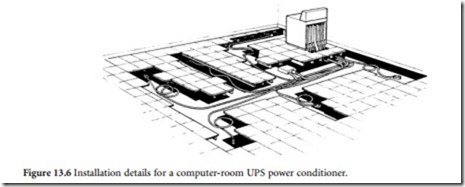
generator that starts as soon as the utility company feed is interrupted. With this arrangement, the batter- ies are called upon to supply operating current for only 30 s or so, until the generator gets up to speed. A UPS system intended to power a computer center is illustrated in Figure 13.6.
Power-Conversion Methods
Solid-state UPS systems that do not employ rotating machinery utilize one of several basic concepts. The design of an inverter is determined primarily by the operating power level. The most common circuit configurations include:
• Ferroresonant inverter
• Delta magnetic inverter
• Inverter-fed L/C tank
• Quasi-square wave inverter
• Step wave inverter
• Pulse-width modulation (PWM) inverter
• Phase modulation inverter
In the following sections an overview of common inverter technologies is given.
Ferroresonant Inverter
Illustrated in Figure 13.7, the ferroresonant inverter is popular for low- to medium-power applications. A ferroresonant transformer can be driven with a distorted, unregulated input voltage and deliver a regulated, sinusoidal output when filtered properly. The ferroresonant transformer core is designed so that the secondary section is magnetically saturated at the desired output voltage. As a result, the output level remains relatively constant over a wide range of input voltages and loads. Capacitors, connected across
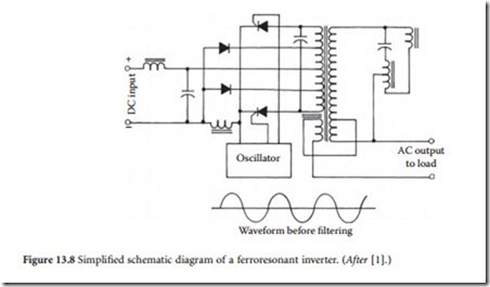
the secondary, help drive the core into saturation and, in conjunction with inductive coupling, provide harmonic filtering. Regulated, sinusoidal three-phase output voltages are derived from two inverters operating into ferroresonant transformers in a Scott-T configuration. The basic ferroresonant inverter circuit, shown in Figure 13.8, consists of an oscillator that controls SCR switches, which feed a ferroresonant transformer and harmonic filter. The saturated operating mode produces a regulated output voltage and inherent current limiting. Efficiency varies from 50 to 83%, depending on the load. Response time of the ferroresonant inverter is about 20 ms.
Although ferroresonant inverters are rugged, simple, and reliable, they do have disadvantages. First, such systems tend to be larger and heavier than electronically controlled inverters. Second, there is a phase shift between the inverter square wave and the output sine wave. This phase shift varies with load magnitude and power factor. When an unbalanced load is applied to a three-phase ferroresonant inverter, the output phases can shift from their normal 120° relationships. This results in a change in line-to-line voltages, even if individual line-to-neutral voltages are regulated perfectly. This voltage imbalance cannot be tolerated by some loads.
Delta Magnetic Inverter
Although most multiphase inverters are single-phase systems adapted to three-phase operation, the delta magnetic inverter is inherently a three-phase system. A simplified circuit diagram of a delta magnetic inverter is shown in Figure 13.9. Inverter modules A1, B1, and C1 produce square wave outputs that are
phase-shifted relative to each other by 120°. The waveforms are coupled to the primaries of transformer T1 through linear inductors. T1 is a conventional three-phase isolation transformer. The primaries of the device are connected in a delta configuration, reducing the third harmonic and all other harmonics that are odd-order multiples of the third. The secondaries of T1 are connected in a wye configuration to pro- vide a four-wire three-phase output. Inductors L4 to L9 form a network connected in a delta configura- tion to high-voltage taps on the secondary windings of T1. Inductors L4 to L6 are single-winding saturating reactors, and L7 to L9 are double-winding saturating reactors. Current drawn by this saturat- ing reactor network is nearly sinusoidal and varies in magnitude, in a nonlinear manner, with voltage variations. For example, if an increase in load tended to pull the inverter output voltages down, the reduced voltage applied to the reactor network would result in a relatively large decrease in current drawn by the network. This, in turn, would decrease the voltage drop across inductors L1 to L3 to keep the inverter output voltage at the proper level. The delta magnetic regulation technique is essentially a three- phase shunt regulator. Capacitors C1–C3 help drive the reactor network into saturation, as well as pro- vide harmonic filtering in conjunction with the primary inductors.
Inverter-Fed L/C Tank
An inductor/capacitor tank is driven by a dc-to-ac inverter, as illustrated in Figure 13.10. The tank circuit acts to reconstruct the sine wave at the output of the system. Regulation is accomplished by varying the capacitance or the inductance to control partial resonance or power factor. Some systems of this type use a saturable reactor in which electronic voltage-regulator circuits control the dc current in the reactor. Other systems, shown in Figure 13.11, use a dc-to-variable-dc inverter/converter to control the UPS out- put through adjustment of the boost voltage. This feature permits compensation for changes in battery level.
Quasi-Square Wave Inverter
Shown in Figure 13.12, the quasi-square wave inverter produces a variable-duty waveshape that must be filtered by tuned series and parallel inductive-capacitive networks to reduce harmonics and form a sinu- soidal output. Because of the filter networks present in this design, the inverter responds slowly to load changes; response time in the range of 150 to 200 ms is common. Efficiency is about 80%. This type of inverter requires voltage-regulating and current-limiting networks, which increase circuit complexity and make it relatively expensive.
Step Wave Inverter
A multistep inverter drives a combining transformer, which feeds the load. The general concept is illustrated in Figure 13.13. The purity of the output sine wave is a function of the number of discrete steps produced by the inverter. Voltage regulation is achieved by a boost dc-to-dc power supply in series with the battery. Figure 13.14 and Figure 13.15 show two different implementations of single-phase units. Each system uses a number of individual inverter circuits, typically three or multiples of three. The inverters are controlled by a master oscillator; their outputs are added in a manner that reduces harmonics, producing a near-sinusoidal output. These types of systems require either a separate voltage regulator on the dc bus or a phase shifter. Response time is about 20 ms. Little waveform filtering is required, and efficiency can be as high as 85%. The step wave inverter, however, is complex and expensive. It usually is found only in large three-phase UPS systems.
Pulse-Width Modulation Inverter
Illustrated in Figure 13.16, the pulse-width modulation circuit incorporates two inverters that regulate the output voltage by varying the pulse width. The output closely resembles a sine wave. Reduced filtering requirements result in good voltage-regulation characteristics. Response times close to 100 ms are typical. The extra inverter and feedback networks make the PWM inverter complex and expensive. Such systems usually are found at power levels greater than 50 kVA.
Phase Modulation Inverter
Illustrated in Figure 13.17, this system uses dc-to-ac conversion through phase modulation of two square wave high-frequency signals to create an output waveform. The waveform then is filtered to remove the carrier signal and feed the load.
Redundant Operation
UPS systems can be configured as either a single, large power-conditioning/backup unit, or as several smaller systems arranged in a parallel redundant or isolated redundant mode. In the parallel redundant mode, the UPS outputs are connected together and share the total load. (See Figure 13.18.) The power- output ratings of the individual UPS systems are selected to provide for operation of the entire load with any one UPS unit out of commission. In the event of expansion of the DP facility, additional UPS units can be added to carry the load. The parallel system provides the ability to cope with the failure of any single unit.
An isolated redundant system, illustrated in Figure 13.19, divides the load among several UPS units. If one of the active systems fails, a static bypass switch will connect the affected load to a standby UPS sys- tem dedicated to that purpose. The isolated redundant system does not permit the unused capacity of one UPS unit to be utilized on a DP system that is loading another UPS to full capacity. The benefit of the isolated configuration is its immunity to systemwide failures.
Output Transfer Switch
Fault conditions, maintenance operations, and system reconfiguration require the load to be switched from one power source to another. This work is accomplished with an output transfer switch. As dis- cussed previously, most UPS systems use electronic (static) switching. Electromechanical or motor- driven relays operate too slowly for most DP loads. Static transfer switches can be configured as either of the following:
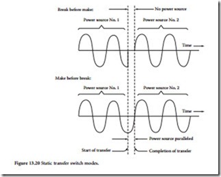
• Break-before-make: Power output is interrupted before transfer is made to the new source.
• Make-before-break: The two power sources are overlapped briefly so as to prevent any interruption in ac power to the load.
Figure 13.20 illustrates each approach to load switching.
For critical-load applications, a make-before-break transfer is necessary. For the switchover to be accomplished with minimum disturbance to the load, both power sources must be synchronized. The UPS system must, therefore, be capable of synchronizing to the utility ac power line (or other appropriate power source).
Battery Supply
UPS systems typically are supplied with sufficient battery capacity to carry a DP load for periods ranging from 5 min to 1 h. Long backup time periods usually are handled by a standby diesel generator. Batteries require special precautions. For large installations, they almost always are placed in a room dedicated to that purpose. Proper temperature control is important for long life and maximum discharge capacity.
Most rectifier/charger circuits operate in a constant-current mode during the initial charge period and automatically switch to a constant-voltage mode near the end of the charge cycle. This provides maximum battery life consistent with rapid recharge. It also prevents excessive battery outgassing and water consumption. The charger provides a float voltage level for maintaining the normal battery charge and sometimes a higher voltage to equalize certain devices.
Four battery types typically are found in UPS systems:
• Semisealed lead calcium. A gel-type electrolyte is used that does not require the addition of water. There is no outgassing or corrosion. This type of battery is used when the devices are integral to small UPS units, or when the batteries must be placed in occupied areas. The life span of a semisealed lead calcium battery, under ideal conditions, is about 5 years.
• Conventional lead calcium. The most common battery type for UPS installations, these units require watering and terminal cleaning about every 6 months. Expected lifetime ranges up to 20 years. Conventional lead-calcium batteries outgas hydrogen under charge conditions and must be located in a secure, ventilated area.
• Lead-antimony. The traditional lead-acid batteries, these devices are equivalent in performance to lead-calcium batteries. Maintenance is required every 3 months. Expected lifetime is about 10 years. To retain their capacity, lead-antimony batteries require a monthly equalizing charge.
• Nickel-cadmium. Advantages of the nickel-cadmium battery includes small size and low weight for a given capacity. These devices offer excellent high- and low-temperature properties. Life expectancy is nearly that of a conventional lead-calcium battery. Nickel-cadmium batteries require a monthly equalizing charge, as well as periodic discharge cycles to retain their capacity. Nickel- cadmium batteries are the most expensive of the devices typically used for UPS applications.


