FDTD Software for the Simulation of Nanostructures
The Basics of the FDTD Simulation Method
Optiwave FDTD (OptiFDTD) is a powerful simulation tool, highly integrated, software that allows computer aided design and simulation of advanced passive photonic components. The OptiFDTD software package is based on the FDTD method. The FDTD method has been established as a powerful engineering tool for integrated and diffractive optics device simulations. This is due to its unique combination of features, such as the ability to model light propagation, scattering and diffraction, and reflection and polarization effects. The method allows for the effective and powerful simulation and analysis of sub-micron (nano-scale) devices with very fine structural details. A sub-micron or nanoscale implies a high degree of light confinement and correspondingly, the large refractive index difference of the materials (mostly semiconductors) to be used in a typical device design [18–20].
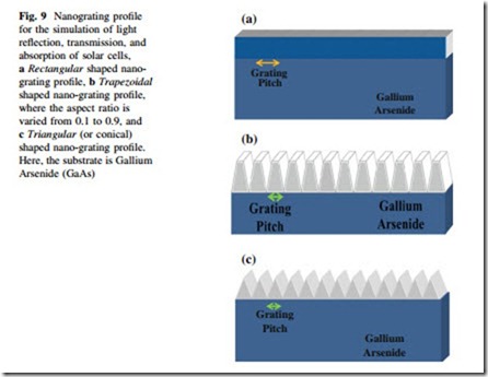
The OptiFDTD software package was developed by Optiwave Inc. This soft- ware is established to aid the user in the design and simulation of advanced passive Fig. 9 Nanograting profile for the simulation of light reflection, transmission, and absorption of solar cells, a Rectangular shaped nano- grating profile, b Trapezoidal shaped nanograting profile, where the aspect ratio is varied from 0.1 to 0.9, and c Triangular (or conical) shaped nano-grating profile. Here, the substrate is Gallium Arsenide (GaAs)
photonic components based on the FDTD method. The FDTD method is used for integrated and diffractive optics simulations due to its ability to model the light propagation, scattering, and diffraction and at the same time monitor light reflection and polarization effects. It can also model material anisotropy and dispersion without any preassumption of field behavior, such as the slowly varying amplitude approximation.
The FDTD method is a simple and intuitive way to solve numerically the partial differential equations. The FDTD method utilizes the central difference approximation to discretize the two Maxwell’s curl equations, namely Faraday’s and Ampere’s laws, both in time and spatial domains, and then it solves the resulting equations numerically to derive the electric and magnetic field distributions at each time step using an explicit leapfrog scheme. The FDTD solution, thus derived, is second-order accurate, and is stable if the time step satisfies the Courant condition. One of the most important attributes of the FDTD algorithm is that it is absurdly parallel in nature because it only requires exchange of information at the interfaces of the sub-domains in the parallel processing scheme.
The Equations of 2D FDTD Method
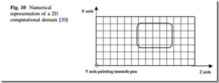
The FDTD approach is based on a direct numerical solution of the time-dependent Maxwell’s curl equations. Such as, the photonic device is laid out in the X–Z plane. The propagation is along the Z-direction. The Y-direction is assumed to be infinite in 2D simulation. This assumption removes all the derivatives from Maxwell’s equations and splits them into two (TE: Transverse Electric and TM: Transverse Magnetic) independent sets of equations. The 2D computational domain is shown in Fig. 10. The space steps are Dx in the X-direction and Dz in the Z-direction of the X-Z plane. Each mesh point is associated with a specific type of material and contains information about its properties, such as refractive index and dispersion parameters [20].
TE Waves for FDTD Simulation
In the 2D TE wave case (Hx, Ey, Hz—nonzero components, propagation along with Z, transverse field variations along with X) in lossless media, Maxwell’s equations can be written in the following form [20]:
where, e = e0er is the dielectric permittivity and l0 is the magnetic permeability of the vacuum. The refractive index is represented by n = H(er).
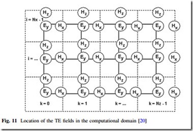
Each field is represented by a 2D array—Ey (i,k), Hx (i,k) and Hz (i,k)— corresponding to the 2D mesh grid as given in Fig. 10. The indices i and k account for the number of space steps in the X- and Z- direction, respectively. For the case of TE waves, the location of the fields in the mesh (computational domain) is shown in Fig. 11.
The TE fields stencil can be explained as follows. The Ey field locations coincide with the mesh nodes given in Fig. 10. In Fig. 11, the solid lines represent the mesh given in Fig. 10. The Ey field is considered to be the center of the FDTD
space cell. The dashed lines form the FDTD cells. The magnetic fields Hx and Hz are associated with cell edges. The locations of the electric fields are associated with integer values of the indices i and k. The Hx field is associated with integer i and (k ? 0.5) indices. The Hz field is associated with (i ? 0.5) and integer k indices. The numerical analogy in Eq. 4 can be derived from the following relationship [20]:
TM Waves for FDTD Simulation
In the 2D TM wave case (Ex, Hy, Ez—nonzero components, propagation along with Z, transverse field variations along with X) in lossless media, Maxwell’s equations take the following form [20]:
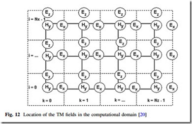
The location of the TM fields in the computational domain (mesh) follows the same philosophy as shown in Fig. 12.
Now, the electric field components Ex and Ez are associated with the cell edges, while the magnetic field Hy is located at the cell center.
Lorentz-Drude Model
Lorentz-Drude Model in Frequency Domain
It has been shown in Ref. [21] that a complex dielectric function for some metals can be expressed in the following form [20]:
This form separates explicitly the intraband effects (usually referred to as free electron effects) from interband effect (usually referred to as bound-electron effects). The intraband part of the dielectric function is described by the well- known free-electron or Drude model in Ref. [22–23].
where, xp is the plasma frequency, m is the number of oscillators with frequency xm and lifetime 1/Cm, where Xp = H(Gm)xm is the plasma frequency as associ- ated with intraband transitions with oscillator strength G0, Gm is related to the oscillator strengths, and damping constant is C0.
The above Lorentz-Drude Model can be expressed as the more general equation
where, er,? is the relative permittivity in the infinity frequency. Xm is the plasma frequency, xm is the resonant frequency, and Cm is the damping factor or collision frequency.
In this general equation, if only the term m = 0 exists, and x0 = 0, then the general equation describes the Drude model as in (8). If only the m = 1,….., M term exists, and X1 = X2 = X3 = ……… = XM; then the general model becomes the Lorentz model as in (9). This model can also work as the separate Drude and Lorentz models.
Reference [21] also provided Lorentz-Drude (LD) parameters for 11 noble metals; their unit is in electron volts. Lorentz-Drude parameters for selected materials contain parameters compiled by Optiwave that describe noble metals.
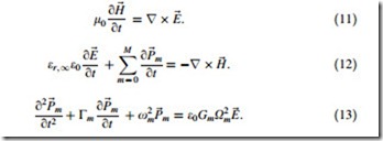
Lorentz-Drude Model in Time Domain
The Lorentz-Drude model shown in (10) is in the frequency domain form. However, the FDTD is a time domain method and therefore it would be suitable for broadband simulations. Therefore, the need to transform (10) to the time domain form so that the FDTD can handle the fullwave-analysis for the Lorentz- Drude material. This transformation to time domain is accomplished using the Polarization philosophy within Maxwell’s equation as given below. The Lorentz- Drude model in time domain can be expressed as follows [20]:
The FDTD algorithm is derived based on the above equation.
However, the FDTD simulation results have demonstrated significant enhancement of light absorption for the design of nano-structured devices [10, 16, 17]. The FDTD algorithm was originally proposed by K. S. Yee in 1966 [18] who introduced a modeling technique to solve the Maxwell equations applying finite difference approach (or mathematics). The FDTD algorithm can directly calculate the value of E (Electric field intensity) and H (magnetic field intensity) at different points in the computational domain (i, j, k) [24]. Since then, it has been used for several applications and many extensions of the basic algorithm have been developed [18–20]. Now, the FDTD method is very much efficient, accurate, and widely used for electromagnetism computations, such as fields and resonant modes.
