Fault Withstand Capability
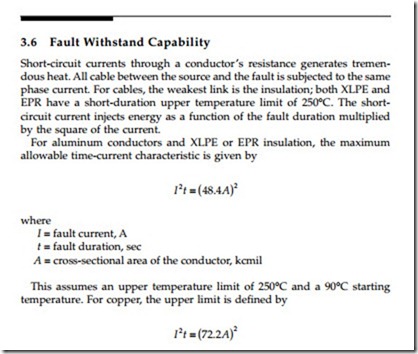
Short-circuit currents through a conductor’s resistance generates tremendous heat. All cable between the source and the fault is subjected to the same phase current. For cables, the weakest link is the insulation; both XLPE and EPR have a short-duration upper temperature limit of 250°C. The short- circuit current injects energy as a function of the fault duration multiplied by the square of the current.
For aluminum conductors and XLPE or EPR insulation, the maximum allowable time-current characteristic is given by
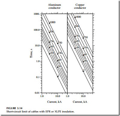
We can plot these curves along with the time-current characteristics of the protecting relay, fuse, or recloser to ensure that the protective devices protect our cables.
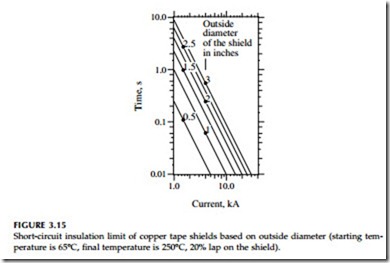
Damage to the shield or the neutral is more likely than damage to the phase conductor. During a ground fault, the sheath may conduct almost as much current as the phase conductor, and the sheath is normally smaller. With a one-third neutral, the cable neutral’s I2t withstand is approximately 2.5 times less than the values for the phase conductor indicated in Figure 3.14 (this assumes a 65°C starting temperature). Having more resistance, a tape shield is even more vulnerable. A tape shield has a limiting time-current characteristic of
where z is 79.1 for sheaths of copper, 58.2 for bronze, 39.2 for zinc, 23.7 for copper-nickel, and 15 for lead [with a 65°C starting temperature and an
upper limit of 250°C; using data from (Kerite Company)]. Figure 3.15 shows withstand characteristics for a 5-mil copper tape shield. The characteristic changes with cable size because larger diameter cables have a shield with a larger circumference and more cross-sectional area. If a given fault current lasts longer than five times the insulation withstand characteristic (at 250°C), the shield reaches its melting point.
In the vicinity of the fault, the fault current can cause considerably more damage to the shield or neutral. With a concentric neutral, the fault current may only flow on a few strands of the conductor until the cable has a grounding point where the strands are tied together. Excessive temperatures can damage the insulation shield, the insulation, and the jacket. In addition, the temperature may reach levels that melt the neutral strands. A tape shield can suffer similar effects: where tape layers overlap, oxidation can build up between tape layers, which insulate the layers from each other. This can restrict the fault current to a smaller portion of the shield. Additionally, where the fault arc attaches, the arc injects considerable heat into the shield or neutral, causing further damage at the failure point. Some additional damage at the fault location must be tolerated, but the arc can burn one or more neutral strands several feet back toward the source.
Martin et al. (1974) reported that longitudinally corrugated sheaths per- form better than wire or tape shields for high fault currents. They also reported that a semiconducting jacket helped spread the fault current to the sheaths of other cables (the semiconducting material breaks down).
Pay special attention to substation exit cables in areas with high fault currents (especially since exit cables are critical for circuit reliability). During a close fault, where currents are high, a reduced neutral or tape shield is most prone to damage.


