Electrical Constants
The following electrical constants are used in the application of power cables.
Positive- and negative-sequence resistance
The resistance of a conductor to positive- and negative-sequence currents is affected by the following factors.
Skin effect: This effect is due to unequal distribution of alternating current (AC) flowing in a conductor because of the tendency of the current to flow more on the outside than inside strands of the con- ductor. This results in a higher resistance to AC than direct current (DC). Usually this effect can be neglected in smaller conductors.
Proximity effect: This effect is due to alternating magnetic flux produced by circulating current in a conductor caused by the current flowing in a neighboring conductor. This effect increases the resistance of a conductor. It can become pronounced where cables are installed parallel to metal beams, plates, walls, and the like.
Sheath currents: The alternating current (AC) flowing in a sheathed single conductor induces voltage in the sheath. Since the sheath is bonded and grounded at both ends, currents flow longitudinally, causing I2R losses. One way to account for these losses is to increase the resistance of the conductor.
Positive- and negative-sequence reactance The reactance of a single lead-sheath conductor to positive- and negative-
sequence current can be calculated by taking into account the effect of sheath currents. It can be expressed mathematically by the following:
where
X1 is the positive-sequence reactance
X2 is the negative-sequence reactance
Xa is the self-reactance of conductor at 1 ft radius
Xd is the reactance of conductor beyond 1 ft radius
Xs is the equivalent reactance value due to sheath currents
For three-phase conductors, Xs can be neglected and the positive and negative reactances are X1 = X2 = Xa + Xd Ω/mile/phase.
Zero-sequence resistance and reactance
When zero-sequence currents flow in the three-phase system, the return
path is usually either through the earth ground, sheath, ground wire, or
a combination of these paths. In actual installation, the following combination of paths should be considered:
1. All currents in the ground, none in sheath
2. All currents in the sheath, none in ground
3. All currents in sheath and ground
When low-voltage cables are installed in magnetic ducts, the zero-sequence resistance and reactance are influenced by the magnetic material surrounding the conductor. No methods have been developed yet to accurately calculate the zero-sequence impedance. However, test data are available to give the required zero-sequence impedance data in standard reference handbooks on transmission and distribution of electrical power for various sizes of cables.
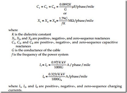
Shunt capacitance reactance
The positive-, negative-, and zero-sequence shunt capacitive reactances of cable are the same and can be expressed mathematically as follows:
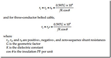
Insulation resistance
The insulation resistance of the cable is very difficult to calculate because of varying insulation properties. However, a generalized formula can be expressed in terms of the power factor (PF) of the insulation system. For single-conductor cable,

