New Power Control Methods Under Unbalanced AC Source
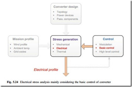
This section targets to improve the power control limits of typical three-phase wind power converter system under unbalanced AC source (e.g., grid or generator with faults). A new series of control strategies which utilizes the zero sequence components are proposed to enhance the power control ability under this adverse condition. The relevant determining factors for analysis are highlighted in Fig. 5.24,
and it can be seen that the electrical behavior influenced by the basic control of wind power converter is mainly focused, although the rest factors may need to be involved in order to establish a proper converter operating condition.
Applicable Conditions and Control Structure
When the voltages become distorted and unbalanced under faults or disturbances, special control methods of the converter which can regulate both the positive and negative sequence currents have been introduced to handle these problems [3–5, 12–15]. However, the resulting performances by these control methods are not satisfactory: either distorted load currents or power oscillations will be introduced, and thereby not only the grid/generator but also the power converter will be further stressed.
The main reason for the unsatisfactory control performances is detailed in Chap. 14. In the typical three-phase three-wire converter structure, there are only four current control freedoms, which are not enough under unbalanced AC source condition because there are six power parameters which need to be controlled [3–5]. Therefore, more control freedoms would be needed in order to improve the control performance of the converter under adverse AC source condition.
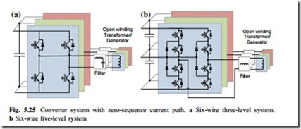
Another type of converter structures which have been presented before for the next generation wind turbines is shown in Fig. 5.25a, b, respectively. Compared to the traditional three-wire structure, this series of converters introduces six wires
b Six-wire five-level system
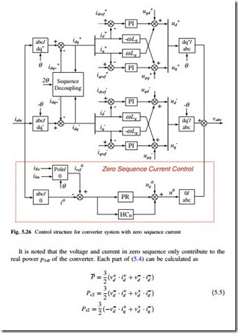
(open winding) and thus zero-sequence current path, which may enable extra two current control freedoms to achieve better control performances. The control dia- gram for the positive, negative, and zero sequence current used for this six-wire converter structure is shown in Fig. 5.26. It is noted that if the converter is used at the grid side in the wind turbine system, the zero sequence current is not injected into the grid but trapped in the typically used d-Y transformer.
Control Ideas and Methods
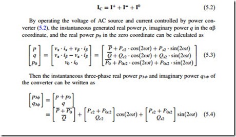
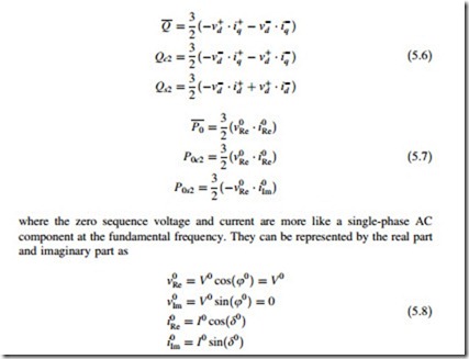
With the zero sequence current, the three-phase currents generated by the converter can be written as [12–17]
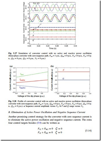
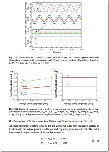
When applying the control targets in (5.9) and (5.10), the corresponding source voltage, load current, sequence current amplitudes, and the instantaneous power delivered by converter are shown in Fig. 5.27, where the grid voltage on phase A is dipping to 0 p.u. It can be seen that by this control strategy, the twice fundamental frequency oscillation of both active and reactive power can be totally eliminated. Moreover, compared to all the control strategies for three-wire system, the ampli- tude of load current in each phase is not further increased, and the current in the faulty phase is smaller than the other two normal phases.
The current amplitude in different sequences and the delivered active/reactive power with relation to the voltage amplitude on the dipping phase are shown in Fig. 5.28a, b, respectively. It is noted that the converter has to deliver positive, negative, and zero sequence currents to achieve this control strategy, and there is no power oscillations for both the active and reactive powers under various voltage dipping severities.
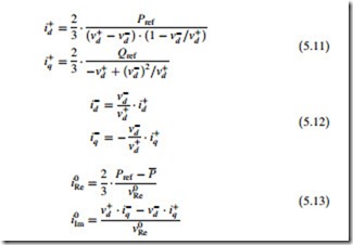
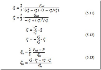
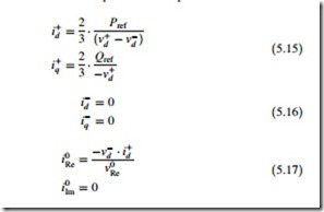
Translating the control targets into (5.9) and (5.14), all the controllable current components of the converter with zero-sequence current path can be calculated as
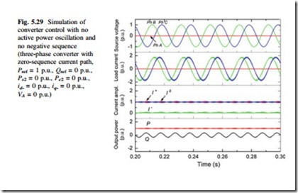
When applying the control targets in (5.9) and (5.14), the corresponding source voltage, load current, sequence current amplitude, and the instantaneous power by converter are shown in Fig. 5.29. It can be seen that by this control strategy, the twice fundamental frequency oscillation of active power can be eliminated, and the load current in the faulty phase is reduced to zero.
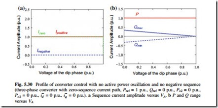
The current amplitude in different sequences and the delivered active/reactive power with relation to the dipping phase voltage are shown in Fig. 5.30a, b, respectively. It is noted that the converter has to deliver constant positive and zero sequence currents to achieve this control strategy under different source voltage dips. The fluctuation of reactive power is maintained in a smaller range (up to
Another group of control strategies for the converter structure in Fig. 5.25 is to eliminate the zero sequence current, as given in (5.18). Meanwhile, another two arbitrary control targets can be added. This series control strategies will result in the same control performances as the typical three-wire converter system, and it could also be used under the normal AC source operation to limit the zero sequence current.
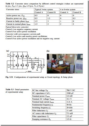
The converter stresses for the active/reactive power oscillations and the current amplitude in the faulty/normal phases are compared in Table 5.2, where different control strategies and converter structures are indicated, respectively. It can be seen that by introducing the converter structures and controls with zero-sequence current path, the power oscillations under unbalanced AC source are significantly reduced; meanwhile, the current amplitude in the normal phases are not further stressed, and the normal phases are not further stressed, and the current stress in the faulty phases is significantly relieved.
D. Experimental Results
The control results by different converter structures and control strategies are validated on a downscale DC-AC converter. As shown in Fig. 5.31, the circuit con- figurations and setup photo are both illustrated. A three-phase two-level converter with corresponding LCL filter is used to interconnect two DC voltage sources and a programmable three-phase AC voltage source. The detailed parameters of the experimental setup are shown in Table 5.3. It is noted that the converter is
controlled to operate at inverter mode, where the active power is flowing from DC source to AC source. By opening and closing a switch shown in Fig. 5.31a, the converter can be shifted between typical three-wire system and four-wire system with zero-sequence current path. The amplitude of phase A voltage in the pro- grammable AC source is adjusted to 0.1 p.u. (22 Vrms) in order to establish an adverse unbalanced condition.
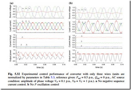
The control performance of the converter with three-wire structure is shown in Fig. 5.32, where the given conditions and the very typical two control strategies are applied, respectively. It can be seen that the experimental results agree well with the analysis and simulation results, where either significant power oscillations or over-loaded currents in the faulty phase are presented.
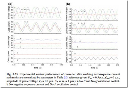
After enabling the zero-current path and proposed controls, the performances of the given converter are shown again in Fig. 5.33, where the same conditions and two control strategies mentioned in Figs. 5.27 and 5.29 are applied, respectively. It can be seen that the experimental results also agree well with the simulation results, where the power oscillations are much more reduced or even totally canceled; meanwhile, the current stress in the faulty phase is significantly relived. These critical performances are hard to be achieved by a single three-wire converter structure using existing control strategies.
