Cable Characteristics
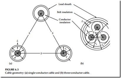
The electrical characteristics of cables are concerned with the electrical constants most commonly required for power system calculations. These electrical constants, such as positive sequence impedance (Z1), negative sequence impedance (Z2), and zero sequence (Z0), are used in the applica- tion of symmetrical components for calculations of short-circuit currents, unbalanced voltages, and their phase relationships among sheaths and conductors, which are important in the calculation of reactance, capacitance, insulation resistance, and dielectric loss. The cable geometry for single- and three-conductor cable is shown in Figure 6.3. The cable
Cable geometry: (a) single-conductor cable and (b) three-conductor cable.
ratings provide the basic information regarding its application and use. A basic knowledge of cable ratings is essential for correct selection and application of cables. Exceeding cable ratings or their misapplication can be hazardous to property and personnel, as well as to successful operation of the plant or facility.
Cable properties
The two properties of cables, as mentioned, are geometry of cables and electrical constants. A general rule is that regardless of the complexity of mutual inductive relations between component parts of individual phases, the method of symmetrical components can be applied rigorously whenever there is symmetry among phases. All three-conductor cables satisfy this condition by the nature of their construction; single conductor cable may or may not.
However, the error is very small when they are treated similarly as three- conductor cables. The space relationship among sheaths and conductors in a cable circuit is a major factor in determining reactance, capacitance, charging current, insulation resistance, dielectric loss, and thermal resistance. The physical characteristics of cables can be determined from the geometry of cables, which is described next.
Geometric mean radius
The geometric mean radius (GMR) is a property usually applied to the conductor alone, and depends on the material and stranding used in its construction. One component of conductor reactance is normally calculated by evaluating the integrated flux linkages both inside and outside the conductor within an overall 12 in. radius. Consider a solid conductor that has some of the flux lines lying within the conductor and contributing to the total flux linkages, even though they link only a portion of the total conductor current. Now consider a tubular conductor having an infinitely thin wall substituted for the solid conductor; it has a flux that would necessarily lie external to the tube. Therefore, a theoretical tubular conductor, to be inductively equivalent to a solid conductor, must have a smaller radius so that the flux linkages present inside the solid conductor, but absent within the tube, will be replaced by additional linkages between the tube surface and the limiting cylinder of 12 in. radius. A solid copper conductor of radius d/2 is equivalent to a tubular conductor radius 0.779d/2. This equivalent radius is called the GMR of the actual conductor. This quantity can be used in reactance calculations with- out further reference to the shape or makeup of the conductor. The factor by which actual radius must be multiplied to obtain GMR varies with stranding and hollow-core construction.
Geometric mean distance (GMD)
Spacing among conductors or between conductors and sheaths is important in determining total circuit reactance. The total flux linkage surrounding a conductor can be divided into two components, one extending inward from
the cylinder of 12 in. radius and the other extending outward from this cylinder to the current return path beyond which there are no net flux linkages.
The flux linkages per unit conductor current between the 12 in. cylinder and the return path are functions of the separation of the conductor and its return path. GMD is therefore a term that can be used in the expression for the external flux linkages, not only in the simple case of two adjacent conductors, where it is equal to the distance between conductor centers, but also in the more complex case where two circuits, each composed of several conductors, are separated by an equivalent GMD.
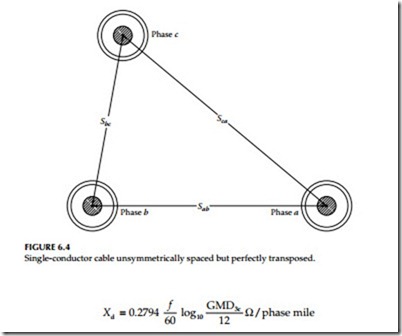
The positive or negative sequence reactance of a three-phase circuit depends on separation among phase conductors. If the conductors are equilaterally spaced, the distance from one conductor center to another is equal to the GMD among conductors for that circuit. The GMD for three- conductor cable is GMD3c = S for an equilateral circuit where S is the dis- tance between each conductor. If the conductors are arranged other than quilaterally as shown in Figure 6.4, but transposed along their length to produce a balanced circuit, the equivalent separation may be calculated by deriving the GMD from the cube root of three distance products. This is expressed as follows:
The component of circuit reactance caused by flux outside a 12 in. radius is widely identified as the reactance spacing factor (Xd) and can be calculated directly from GMD.
When equivalent separation is less than 12 in., as can occur in cable circuits, the reactance spacing factor is negative so as to subtract from the component of conductor reactance due to flux out to a 12 in. radius.
The zero-sequence reactance of a three-phase circuit may depend on spacing among conductors and sheath.
Geometric factor
The relation in space between the cylinders formed by the sheath internal surface and conductor external surface in a single-conductor lead-sheath cable can be expressed as a geometric factor. The factor is applicable to the calculation of cable characteristics such as capacitance, charging current, dielectric loss, leakage current, and heat transfer. The mathematical expression for geometric factor G in a single-conductor cable is


