Preventive Maintenance of Transformers
The objective of this section is to outline the recommended work practices that are usually performed for preventive maintenance of transformers. The recommended procedures specified in this chapter do not pertain to the major overhaul and repair of a transformer. However, many tasks performed during routine maintenance and major overhaul of a transformer may be the same. The maintenance practices discussed in this section are applicable to a transformer that has not reached an advanced stage of deterioration. Moreover, these recommendations are written for the average conditions under which the transformer is required to perform and operate. It is further implied that all personnel associated with the maintenance are suitably trained and have experience in the maintenance of transformers.
The recommended practices offered in this section are similar to those that manufacturers recommend for their equipment. If detailed instructions are required, the reader should consult the instructions manual of the manufacturer. The preventative maintenance of transformer involves rou- tine inspection, adjustment, testing, minor repairs, and special handling instructions. In addition, the trouble-free operation of the equipment over its life is dependent upon proper installation, operation, and maintenance, which are discussed in Section 5.7.1.
Transformer Installation, Acceptance, and Maintenance
The successful operation of transformers is dependent on proper installation, loading, and maintenance, as well as on proper design and manufacture. As is with all electrical apparatus, neglecting of certain fundamental requirements may lead to serious troubles, if not to the loss of the equipment. The objective of transformer maintenance philosophy can be described as follows:
Unscheduled Maintenance
This philosophy is based on reactionary mode of operation. That is to say, maintain the equipment when it breaks down, otherwise leave it alone.
Ordinary Maintenance
This philosophy subscribes to making irregular visual inspection and making repairs, adjustments, and replacements as necessary.
Protective Maintenance
This philosophy consists of performing preventive maintenance, predictive maintenance, and corrective maintenance. The preventive maintenance involves schedule maintenance and testing on a regular basis. Predictive main- tenance involves additional monitoring and testing, where as corrective maintenance involves repairing and restoring transformer integrity to its origi- nal condition when degraded conditions are discovered.
The objective of the protective maintenance of transformers is to control and prevent severe oil and winding (paper) insulation deterioration. Mineral oil and paper insulation of the winding are affected by moisture, oxygen, heat, and other catalytic agents such as copper, iron, electric stress, and so on. The end result is that oxidation takes place in the oil which leads to sludging of the transformer. In sealed units ingress of moisture via atmo- sphere or seal leaks must be prevented. Moisture will reduce the dielectric strength of both the oil and the winding insulation systems. In addition, excessive heating of the transformer will cause the paper (winding insula- tion) to decompose (accelerate aging) which in-turn produces moisture (i.e., break up of cellulose fibres results in freeing hydrogen and oxygen atoms which combine to form H2O). Increased moisture formed in the paper not only reduces the insulating strength of the paper but also, as temperature rises, the moisture will migrate from the paper insulation to the oil and decreasing its dielectric strength.
The first step is to build transformer designs to keep moisture and oxygen out of transformers. The next step is to operate transformers so that they are not operated beyond their temperature ratings and limits. In addition to the above, the severity of deterioration should be controlled by monitoring and testing transformer insulation systems on periodic basis, and take corrective actions to restore transformer to its original condition. This philosophy can be summarized by the following:
1. Control transformer heat
2. Inspect and maintain transformer auxiliary devices
3. Test and maintain transformer insulation systems
4. Maintain transformer bushing insulation
5. Maintain transformer protective coating
These topics are discussed next under installation, maintenance, and testing of transformers. The transformers are divided into dry and liquid types for the purposes of this chapter.
Dry-Type Transformers
Installation
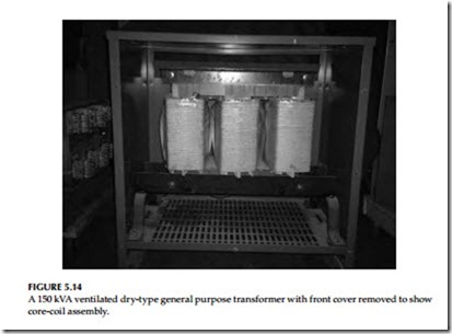
Factors that should be kept clearly in mind in locating dry-type transformers are accessibility, ventilation, and atmospheric conditions. Ventilated dry-type transformers (Figure 5.14) normally are designed for application indoors in dry locations. They will operate successfully where the humidity may be high, but under this condition it may be necessary to take precautions to keep them dry if they are shut down for appreciable periods. Locations where there is dripping water should be avoided. If this is not possible, suitable protection should be provided to prevent water from entering the transformer case. Precautions should be taken to guard against accidental entrance of water, such as might occur from an open window, by a break in a water or steam line, or from use of water near the transformers. Adequate ventilation is essential for the proper cooling of transformers. Clean, dry air is desirable. Filtered air may reduce maintenance if the location presents a particular problem. When transformers are installed in vaults or other restricted spaces, sufficient ven- tilation should be provided to hold the air temperature within established limits when measured near the transformer inlets. This usually will require a minimum of 100 ft3 of air per minute per kilowatt (kW) of transformer loss. The area of ventilating openings required depends on the height of vault. The location of openings, and the maximum loads to be carried by the transformers. For self-cooled transformers, the required effective area should be at least
1 ft for each inlet and outlet per 100 kVA of rated transformer capacity, after deduction of the area occupied by screens, gratings, or louvers.
Ventilated dry-type transformers should be installed in locations free from unusual dust-producing mediums or chemical fumes. Transformers above 75 kVA should be located at least 12 in. from walls or other obstructions that might prevent free circulation of air through and around each unit. The distance between adjacent transformers should not be less than this value. Smaller transformers can be mounted directly on the wall but should still be mounted at least 12 in. apart. Also, accessibility for maintenance should be taken into account in locating a transformer. If the transformer is to be located near combustible materials, the minimum separations established by the National Electrical Code (NEC) should be maintained.
The transformer case is designed to prevent the entrance of most small animals and foreign objects. However, in some locations it may be necessary to give consideration to additional protection. In general, a flat, level indus- trial floor is adequate and no special preparation is necessary because of the base construction used on these transformers, which completely eliminates the complicated process of grouting sills into concrete floors. If noise is a factor in the location and operation of any transformer, special consideration should be given to the installation of the equipment.
The impulse strength of these transformers is less than that of liquid immersed units of the same voltage class. If there is any likelihood that trans- formers will be exposed to lightning or severe switching surges, adequate protective equipment should be provided.
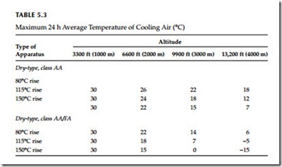
Transformers of standard temperature rise are designed to operate at altitudes up to and including 3300 ft. Dry-type transformers are dependent upon air for dissipation of their heat losses; consequently, the effect of decreased air density due to high altitude will increase the transformer tem- perature. Standard transformers can be used at altitudes greater than 3300 ft if the load to be carried is reduced below nameplate rating as follows:
If the transformer is dry type, self-cooled, class AA, reduce the nameplate rating by 0.3% for each 330 ft above the altitude of 3300 ft.
If the transformer is dry type, forced air cooled, class AA/FA, reduce the nameplate rating by 0.5% for each 330 ft above the altitude of 3300 ft.
If the maximum 24 h average temperature of the cooling air is reduced below design levels, the altitude limitation of 3300 ft can be safely exceeded without reducing the nameplate rating of the transformer within the limita- tions of Table 5.3.
Inspection
New transformers should be inspected for damage during shipment when received. Examination should be made before removing from cars or trucks, and if any injury is evident or any indication of rough handling is visible, a claim should be filed with the carrier at once and the manufacturer should be notified.
Subsequently, covers or panels should be removed and an internal inspec- tion made for injury or displacement of parts, loose or broken connections, cracked porcelain, dirt or foreign material, and for the presence of free water or moisture. Corrective measures should be taken where necessary. Shipping braces should be removed if provided. After a transformer is moved, or if it is stored before installation, this inspection should be repeated before placing the transformer in service.
After making all the necessary primary and secondary connections, the transformer should be thoroughly inspected. Before placing in service, the operation of fans, motors, thermal relays, and other auxiliary devices should be checked. All bolted connections that may have loosened in shipment must be tightened before energizing. The case and core assembly of these trans- formers should be permanently and adequately grounded.
Acceptance Tests
After the transformer has been installed, the following tests should be con- ducted for acceptance:
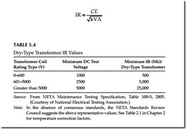
Insulation resistance (IR) test: The IR test is of value for future comparative purposes and also for determining the suitability of the transformer of ener- gizing or application of the high-potential (hi-pot) test. The IR test must be successfully completed for factory warranty to be valid. The IR test must be conducted immediately prior to energizing the transformer or beginning the high potential test.
These values, corrected to factory test temperature of 20°C, must be either 1000 MΩ or equal to or greater than the values shown in the Table 5.4, or a minimum of one half or more of factory test values. If the corrected test values at 20°C are less than the minimum of the values discussed above, then the transformer insulation condition is questionable. In the absence of reliable previous test data, the following formula may be used for single-phase trans- formers, or single winding of a three-phase transformer for calculating the IR values.
where
IR is the minimum 1 min 500 V DC IR in MΩ from winding to ground, with other winding or windings guarded, or winding to winding with core guarded
C = 30 at 20°C measurements (C = 16 for tests of winding with other winding or windings grounded)
E is the voltage rating of winding under test
kVA is the rated capacity of winding under test
If the transformer under test is of the three-phase type, and all three indi- vidual windings are being tested as one, then:
E is the voltage rating of one of the single-phase windings (phase- to-phase for delta-connected units and phase-to-neutral for star-connected units kVA is the rated capacity of the three-phase winding under test Polarization index (PI) test: This is an extension of the IR test. In this test, the two IR measurements are taken, the first reading at 1 min and the second reading at 10 min. Then the ratio of the 10 min reading to 1 min reading is calculated to give the PI dielectric absorption value. A PI of winding-to-winding and winding-to-ground should be deter- mined. A PI below 2 is indicative of insulation deterioration and cause for further investigation.
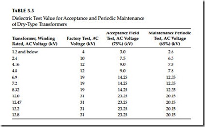
AC hi-pot (dielectric) test: The dielectric test imposes a stress on the insulation since the dielectric test voltage is higher than the normal operating voltage. The IR test must be successfully completed imme- diately before performing the dielectric test to prevent the possibility of transformer failure due to moisture. The dielectric test supple- ments the IR tests by determining the suitability of the transformer for operation at rated voltage. Field test voltages should not exceed 75% of factory test values. The hi-pot test set must be variable to allow a gradual increase of test voltage from zero and a gradual decrease after the test is completed. These test values are shown in Table 5.5.
Transformer turns ratio (TTR) test: The TTR test is used to determine the turns ratio of the transformer. It measures the number of turns of the primary winding with respect to the number of turns in secondary winding. The accepted values of the TTR test shall be not greater than 0.5% as compared with calculated values.
Insulation power factor (PF) (dissipation factor) test: This test measures the watt loss in the insulation under test. Since it is an AC voltage test, it accurately indicates the wetness of the winding insulation and corona problems. This test can be conducted as PF tip-up test for dry type transformers to further distinguish between a moisture or car- bonization problem (see Chapter 3).
Like other electric equipment, these transformers require maintenance from time to time to assure successful operation. Inspection should be made at regular intervals and corrective measures taken when necessary to assure the most satisfactory service from this equipment. The frequency of inspection depends on operating conditions. For clean, dry locations, an inspection annually, or after a longer period, may be sufficient. However, for other loca- tions, such as may be encountered where the air is contaminated with dust or chemical fumes, an inspection at 3 or 6 month intervals may be required. Usually, after the first few inspection periods, a definite schedule can be set up based on the existing conditions.
With the transformer de-energized, covers over openings in the case should be removed. Inspections should be made for dirt, especially accumulations in insulating surfaces or those which tend to restrict air flow, for loose connec- tions, for the condition of tap changers or terminal boards, and for the general condition of the transformer. Observation should be made for signs of over- heating and of voltage creepage over insulating surfaces, as evidenced by tracking or carbonization. Evidence of rusting, corrosion, and deterioration of the paint should be checked and corrective measures taken where necessary. Fans, motors, and other auxiliary devices should be inspected and serviced.
Cleaning: If excessive accumulations of dirt are found on the transformer windings or insulators when the transformer is inspected, the dirt should be removed to permit free circulation of air and to guard against the possibility of insulation breakdowns. Particular attention should be given to cleaning top and bottom ends of winding assemblies and to cleaning out ventilating ducts.
The windings may be cleaned with a vacuum cleaner, blower, or with compressed air. The use of a vacuum cleaner is preferred as the first step in cleaning, followed by the use of compressed air or nitrogen. The com- pressed air or nitrogen should be clean and dry and should be applied at a relatively low pressure (not over 25 psi). Lead supports, tap changers and terminal boards, bushings, and other major insulating surfaces should be brushed or wiped with a dry cloth. The use of liquid cleaners is undesirable because some of them have a solvent or deteriorating effect on most insu- lating materials.
Testing for routine maintenance: Following are the tests that are required for routine maintenance of dry-type transformers.
• IR test of winding-to-winding and winding-to-ground. This test is similar to the test listed under installation and acceptance.
• Dielectric absorption test should be made winding-to-winding and winding-to-ground for 10 min. The PI should be above 2.0 for accept- able limits.
• Turns ratio test (TTR) should be conducted similarly to that under acceptance.
• AC overpotential test should be made on all high- and low-voltage windings-to-ground. This is an optional test for routine maintenance testing. The recommended values of test voltage are shown in Table 5.4.
• Insulation PF test can be conducted for each winding-to-ground and winding-to-winding. The acceptable value is less than 3%.
Drying-Out Methods
For the purpose of drying out, transformers can be considered as consisting of core and coil assembly. When it is necessary to dry out a transformer before installation or after an extended shutdown under relatively high humidity conditions, one of the following methods may be used.
• External heat
• Internal heat
• External and internal heat
Before applying any of these methods, free moisture should be blown or wiped off the windings to reduce the time of the drying period.
Related posts:
Incoming search terms:
- preventive maintenance of transformer
- how to maintain a transformer
- preventive maintenance of transformers
- how to perform routine maintenance on a power transformer
- preventive and routine maintenance of transformer
- maintenance of transformer
- how to maintain transformer
- transformer maintenance checklist
- transformer maintenance
- unscheduled maintenance of transformer
- routine maintenance of transformer
- maintence on a dry transformer
- planned maintenance of transformer
- preventive testing of transformer
- Transformer preventive maintenance
- electrical maintenance table
- preventive maintenance
- preventive maintenance done on tramsformers
- preventive maintenance for transformer
- preventive maintenance on transformers#spf=99
- transformer daily maintenance
- transformer check list
- preventive maintenance of trasnsformer
- preventive maintenance on transformers
- testing and maintaince of transformers
- preventive maintenance regarding transformers
- preventive of transformer
- state the maintenance procedure on 33KVA transformer?
- rputine maintenance test on transformer
- routine maintenance of transforme4
- preventive maintanance schedule of three phase transformer
- preventive and routine maintenance of three phase transformer
- maintenance of a transformer
- maintainance of a transformr
- how to schedule maintenance for transformer
- how to mainten transfermer
- general maintaince in transfermer
- dry type transformer corrective maintenance
- different maintenance procedure of a 3 phase transformer
- Which is not a preventive maintenance schedule of a transformer?
- maintenance of oil transformer
- maintenance of transformer chapter
- preventive and mantainance transformer
- preventive and breakdown maintenance of transformer
- preventative maintenance of Transformer
- predictive maintaince of transformer com
- Perform general preventive mentance on transformer
- on site checklist oil immersed transformer maintenance
- maintenance philosophy of transformer
- maintenance of transformer daily


