Power Electronics
Introduction
The modern age of power electronics began with the introduction of thyristors in the late 1950s [1]. There are now a number of power devices available for high-power and high-frequency applications. The most notable include:
• Gate turn-off (GTO) thyristor
• Power Darlington transistor
• Power MOSFET
• Insulated-gate bipolar transistor (IGBP)
These power devices are used primarily as switches to convert energy from one form to another. They are used in motor control systems, uninterruptible power supplies, high-voltage dc transmission, ac-to-dc power supplies, induction heating, and other power-conversion applications.
Thyristor Devices
The thyristor, also called a silicon-controlled rectifier (SCR), is basically a four-layer three-junction pnpn device [1]. It has three terminals: anode, cathode, and gate. The device is turned on by applying a short pulse across the gate and cathode. After the device turns on, the gate loses its control to turn off the device. The turn-off is achieved, instead, by applying a reverse voltage across the anode and cathode. The thyristor volt ampere characteristics are shown in Figure 8.1.
There are basically two classifications of thyristors: converter grade and inverter grade. The difference between a converter-grade and an inverter-grade thyristor is the low turn-off time (on the order of a few microseconds) for the latter. Converter-grade thyristors are slower and are used in natural commutation (or phase-controlled) applications. Inverter-grade thyristors are used in forced commutation applications such as dc-dc choppers and dc-ac inverters. Inverter-grade thyristors are turned off by forcing the current to zero using an external commutation circuit. This requires additional commutating components, thus resulting in additional losses in the inverter.
Thyristors are rugged devices in terms of transient currents (di/dt and dv/dt capability). The forward voltage drop in a thyristor typically is about 1.5 to 2 V; even at high currents on the order of 500 A, it seldom exceeds 3 V. Although the forward voltage determines the on-state power loss of the device at any given cur- rent, the switching power loss becomes a dominating factor affecting the device junction temperature at high operating frequencies. Thus, the maximum switching frequencies possible using thyristors are limited in comparison with many other power devices. Thyristors are commonly available at ratings of up to 6000 V, 3500 A.
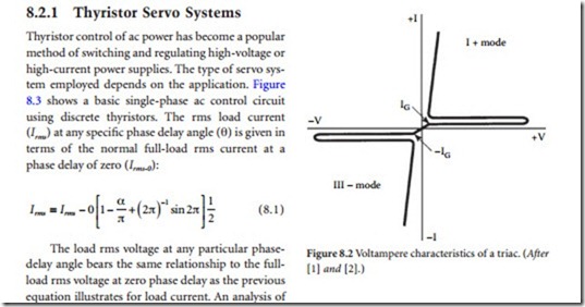
A triac is functionally a pair of converter-grade thyristors connected in an antiparallel arrangement. The triac volt-ampere characteristics are shown in Figure 8.2. Because of the physical integration of the device, the triac has poor reapplied dv/dt capability, poor gate current sensitivity at turn-on, and a longer turn-off time, relative to a pair of equivalent-rating thyristors. Triacs are mainly used in phase control appli- cations such as ac regulators for lighting and fan control, and in solid-state ac relays.
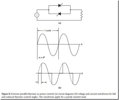
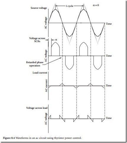
the mathematics shows that although the theoretical delay range for complete control of a resistive load is 0 to 180°, a practical span of 20 to 160° gives a power-control range of approximately 99% to 1% of maximum output to the load. Figure 8.4 illustrates typical phase-control waveforms.
The circuit shown in Figure 8.3 requires a source of gate trigger pulses that must be isolated from each other by at least the peak value of the applied ac voltage. The two gate pulse trains must also be phased 180° with respect to each other. Furthermore, the gate pulse trains must shift together with respect to the ac supply voltage phase when power throughput is adjusted.
Some power-control systems use two identical, but isolated, gate pulse trains operating at a fre- quency of twice the applied supply voltage (120 Hz for a 60 Hz system). Under such an arrangement, the forward-biased thyristor will fire when the gate pulses are applied to the SCR pair. The reverse- biased thyristor will not fire. Normally, it is considered unsafe to drive a thyristor gate positive while its
anode-cathode is reverse-biased. In this case, however, it may be permissible because the thyristor that is fired immediately conducts and removes the reverse voltage from the other device. The gate of the reverse-biased device is then being triggered on a thyristor that essentially has no applied voltage.
Inductive Loads
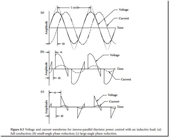
The waveforms shown in Figure 8.5 illustrate effects of phase control on an inductive load. When induc- tive loads are driven at a reduced conduction angle, a sharp transient change of load voltage occurs at the end of each current pulse (or loop). The transients generally have no effect on the load, but they can be dangerous to proper operation of the thyristors. When the conducting thyristor turns off, thereby discon- necting the load from the ac line supply, the voltage at the load rapidly drops to zero. This rapid voltage change, in effect, applies a sharply rising positive anode voltage to the thyristor opposing the device that has been conducting. If the thyristor dv/dt rating is exceeded, the opposing device will turn on and con- duction will take place, independent of any gate drive pulse.
A common protective approach involves the addition of a resistor-capacitor (RC) snubber circuit to control the rate of voltage change seen across the terminals of the thyristor pair. (See Figure 8.6.) When- ever a thyristor pair is used to drive an inductive load, such as a power transformer, it is critically impor- tant that each device fires at a point in the applied waveform exactly 180° relative to the other. If proper timing is not achieved, the positive and negative current loops will differ in magnitude, causing a dc cur- rent to flow through the primary side of the transformer. A common trigger control circuit should, there- fore, be used to determine gate timing for thyristor pairs.
Applications
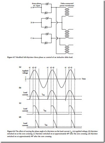
Several approaches are possible for thyristor power control in a three-phase ac system. The circuit shown in Figure 8.7 consists of essentially three independent, but interlocked, single-phase thyristor controllers. This circuit is probably the most common configuration found in industrial equipment.
In a typical application, the thyristor pairs feed a power transformer with multitap primary wind- ings, thereby giving the user an adjustment range to compensate for variations in utility company line voltages from one location to another. A common procedure specifies selection of transformer tap posi- tions that yield a power output of 105% when nominal utility company line voltages are present. The thyristor power-control system then is used to reduce the angle of conduction of the SCR pairs as necessary to cause a reduction in line voltage to the power transformer to yield 100% rated power output from the power supply. A servo loop from a sample point at the load can be used to automatically compensate for line-voltage variations. With such an arrangement, the thyristors are kept within a reasonable degree of retarded-phase operation. Line voltages will be allowed to sag 5% or so without affecting the dc supply output. Utility supply voltage excursions above nominal value simply will result in delayed triggering of the SCR pairs.
The effect of varying the conduction phase angle of a thyristor on the load current is illustrated in Figure 8.8. Note how the current Iavg decreases as the conduction angle is reduced from 180°.
Thyristor control of high-power loads (200 kW and above) typically uses special transformers that provide 6- or 12-phase outputs. Although they are more complicated and expensive, such designs allow additional operational control, and
wye-configured transformer secondary. A second bridge, consisting of six diodes, is connected to low- voltage taps on the same transformer. When the SCRs are fully on, their output is at a higher voltage than the diode bridge. As a result, the diodes are reverse-biased and turned off. When the SCRs are partially on, the diodes are free to conduct. The diodes improve the quality of the output waveform during low- voltage (reduced conduction angle) conditions. The minimum output level of the supply is determined by the transformer taps to which the diodes are connected.
A thyristor-driven, three-phase power-control circuit is shown in Figure 8.10. A single-phase power- control circuit is shown in Figure 8.11.
Triggering Circuits
Accurate, synchronized triggering of the gate pulses is a critical element in thyristor control of a three- phase power supply. The gate signal must be synchronized properly with the phase of the ac line that it is controlling. The pulse also must properly match the phase angle delay of the gates of other thyristors in the power-control system. Lack of proper synchronization of gate pulse signals between thyristor pairs can result in improper current sharing (current hogging) among individual legs of the three-phase supply.
The gate circuit must be protected against electrical disturbances that could make proper operation of the power-control system difficult or unreliable. Electrical isolation of the gate is a common approach.
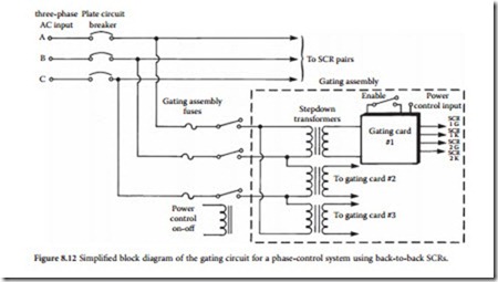
Standard practice calls for the use of gate pulse transformers in thyristor servo system gating cards. Pulse transformers are ferrite-cored devices with a single primary winding and (usually) multiple secondary windings that feed, or at least control, the individual gates of a back-to-back thyristor pair. This concept is illustrated in Figure 8.12. Newer thyristor designs may use optocouplers (primarily for low-power sys- tems) to achieve the necessary electrical isolation between the trigger circuit and the gate.
It is common practice to tightly twist together the leads from the gate and cathode of a thyristor to the gating card assembly. This practice provides a degree of immunity to high-energy pulses that might inadvertently trigger the thyristor gate. The gate circuit must be designed and configured carefully to reduce inductive and capacitive coupling that might occur between power and control circuits. Because of the high di/dt conditions commonly found in thyristor-controlled power circuits, power wiring and control (gate) wiring must be separated physically as much as possible. Shielding of gating cards in metal card cages is advisable.
Equipment manufacturers use various means to decrease gate sensitivity to transient sources, including placement of a series resistor in the gate circuit or a shunting capacitor between the gate and cathode. A series resistor has the effect of decreasing gate sensitivity, increasing the allowable dv/dt of the thyristor, and reducing the turn-off time, which simultaneously increases the required holding and latch- ing currents. The use of a shunt capacitor between the gate and cathode leads reduces high-frequency noise components that might be present on the gate lead and increases the dv/dt withstand capability of the thyristor. The application of these techniques is the exclusive domain of the design engineer. Users should not consider modifying a design without detailed consultation with the engineering department of the original equipment manufacturer.
Control Flexibility
Thyristor servo control of a high-voltage or high-current power supply is beneficial to the user for a number of reasons. First is the wide control over ac input voltages that such systems provide. A by-prod- uct of this feature is the capability to compensate automatically for line-voltage variations. Other benefits include the capability to soft-start the dc supply. Thyristor control circuits typically include a ramp gen- erator that increases the ac line voltage to the power transformer from zero to full value within 2 to 5 s. This prevents high-surge currents through rectifier stacks and filter capacitors during system startup.
Although thyristor servo systems are preferred over other power-control approaches from an opera- tional standpoint, they are not without their drawbacks. The control system is complex and can be dam- aged by transient activity on the ac power line. Conventional power contactors are simple and straightforward. They either make contact or they do not. For reliable operation of the thyristor servo system, attention must be given to transient suppression at the incoming power lines.
Gate Turn-Off Thyristor
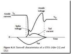
The GTO is a power switching device that can be turned on by a short pulse of gate current and turned off by a reverse gate pulse [1]. The required reverse gate cur- rent amplitude is dependent on the anode current to be turned off. Hence, there is no need for an external commutation cir- cuit to turn off the device. Because turn- off is provided by bypassing carriers directly to the gate circuit, the turn-off
aspects are proper design of the gate turn-off circuit and the snubber circuit. The GTO has poor turn-off current gain, on the order of 4 to 5. For example, a 2000 A peak current GTO may require as high as 500 A of reverse gate current. Also, the GTO has a tendency to latch at high temperatures (above approxi- mately 125ºC). GTO devices are commonly available for operation up to 4500 V at 2500 A.
Reverse-Conducting Thyristor
In typical inverter applications, a diode in antiparallel is connected to the thyristor for commutation/ freewheeling purposes. In a reverse-conducting thyristor (RCT), the diode is integrated with a fast switch- ing thyristor in a single silicon chip [1]. Thus, the number of power devices in a given circuit can be reduced. This integration yields a substantial improvement in the static and dynamic characteristics of the device, as well as improved overall circuit performance.
The RCT is designed mainly for specific applications such as traction drives. The antiparallel diode limits the reverse voltage across the thyristor to 1 to 2 V. Also, because of the reverse recovery behavior of the diodes, the thyristor may see very high reapplied dv/dt when the diode recovers from its reverse volt- age. This necessitates use of large RC snubber networks to suppress the voltage transients. As the range of application of thyristors and diodes extends into higher frequencies, their reverse recovery charge becomes increasingly important. High reverse recovery charge results in high power dissipation during switching.
Asymmetrical Silicon-Controlled Rectifier
The asymmetrical silicon-controlled rectifier (ASCR) has a forward blocking capability similar to an inverter-grade thyristor, but a limited reverse blocking capability (about 20 to 30 V) [1]. The ASCR has an on-state voltage drop of about 25% less than an inverter-grade thyristor of a similar rating. The ASCR features a fast turn-off time, and so it can work at higher frequencies than typical SCRs. Because the turn- off time is reduced by a factor of nearly 2, the size of the commutating components can be halved. The switching losses, therefore, also are reduced.
Gate-assisted turn-off techniques can be used to further reduce the turn-off time of an ASCR. The application of a negative voltage to the gate during turn-off helps to evacuate stored charges in the device and aids the recovery mechanism. This will — in effect — reduce the turn-off time by a factor of up to 2 over the conventional device.
Fusing
Current-limiting is a basic method of protection for thyristors operated from the utility ac line. The device typically used for breaking fault currents is either a fuse or a circuit breaker. Some designs incor- porate both components. Semiconductor fuses often are used in conjunction with a circuit breaker to pro- vide added protection. Semiconductor fuses operate more rapidly (typically within 8 ms) and more predictably than common fuses or circuit breakers. Surge currents caused by a fault can destroy a semi- conductor device, such as a power thyristor, before the ac line circuit breaker has time to act. Manufac- turers of semiconductor fuses and thyristors usually specify in their data sheets the I2t ratings of each device. Because the thyristor rating normally assumes that the device is operating at maximum rated cur- rent and maximum junction temperature (conditions that do not represent normal operation), a safety factor is ensured.
Related posts:
Incoming search terms:
- inverter grade thyristor
- Difference between converter grade scr and inverter grade scr
- conduction angle and reverse recovery charge of a SCR
- inverter grade thyristor theory
- difference between converter grade and inverter grade scr
- converter grade scr
- converter grade thyristor
- Power ratings of converter grade scr and inverter grade scr
- Symbol of the inverter grade thyristor
- inverter grade scr
- converter grade and inverter grade
- Simple thyristors operation Circuit
- inveter grade thyristor
- inverter grade scrs are used in
- inverter grade scrs
- the difference between thyristor and di
- what is the turn off time for converter grade scr and inverter grade scrs
- what is the meaning of converter grade of scr
- what is Converter grade and inverter grade thyristors
- turn on turn off of inverter grade fast thyristor
- Turn off times of converter grade and inverter grade scr
- turn off time of converter grade scr are normally in range of
- thyristors are classified as inverter grade or convertor grade based on
- the turn off time of the converter grqde Scr are normally in range of?
- inverter grade or converter grade thyristor
- Inverter grade fast thyriston
- converter grade of scr
- CONVERTER GRADE SCR USED IN
- converter grade thyristors
- converter grade thyristors are used in
- conveter grade and inverter grade thyristor
- coverter grade and invertet grade
- define inverter grade scr
- difference between converter and inverter scr
- difference between converter gra
- difference between converter grade scr & inverter grade scr
- difference between inverter grade and converter grade scrs
- difference between inverter grade SCR and converter grade Scr
- differenciate between converter grade and inverter
- differnce between converter grade scr and inverter grade scr
- distinguish converter grade and inverter grade thyristort
- for inductive load why train of short pulses are used for thyristor
- how converter grade scr and inverter grade scr are classified
- converter grade and inverter grade thyristor pdf

