Power-System Protection
Transient-protection methods for a commercial/industrial facility vary considerably, depending on the size and complexity of the plant, the sensitivity of equipment at the facility, and the extent of transient activity present on the primary power lines. Figure 16.5 shows one approach to transient suppression for a transmission facility. Lightning arresters are built into the 12 kV-to-208 V, three-phase, pole-mounted transformer. The service drop comes into the meter panel and is connected to a primary lightning arrester and a primary varistor. The circuit shown is duplicated three times for a three-wire wye (208 V phase-to- phase, 120 V phase-to-neutral) power system.
The primary arrester and varistor are placed at the service drop input point to protect the main circuit breaker and power-system wiring from high-voltage transients that are not clipped by the lightning arrester at the pole or by the varistors later in the circuit path. The primary varistor has a higher maxi- mum clamp voltage than the varistors located after the main breaker, causing the devices downstream to carry most of the clamp-mode current when a transient occurs (assuming low system inductance). If the main circuit breaker opens during a transient disturbance, the varistor at the service drop entrance will keep the voltage below a point that could damage the breaker or system wiring.
Placing overvoltage protection before the main service breaker can be considered only when the service drop transformer feeds a single load and when the transformer has transient protection of its own, including lightning arresters and primary-side fuses. Consult the local power company before placing any transient-suppression devices ahead of the main breaker.
Transient protection immediately after the main breaker consists of a secondary varistor and a capacitor between each leg and neutral. A 47 Ω, 10 W series resistor protects the circuit if the capacitor fails. It also reduces the resonant effects of the capacitor and ac distribution-system inductance. The varistor clips overvoltages as previously described, and the resistor-capacitor network helps eliminate high-frequency transients on the line. The capacitor also places higher capacitive loading on the secondary of the utility company step-down transformer, reducing the effects of turn-on spikes caused by capacitive coupling between the primary and the secondary of the pole- or surface-mounted transformer.
As an extra measure of protection, a supplemental varistor and RC snubber are placed at the primary power input to the load. Transient suppressors are placed as needed at the ac power-distribution panel and circuit-breaker box.
Staging
The transient-suppression system shown in Figure 16.5 uses a technique known as staging of protection components. An equivalent circuit of the basic system is shown in Figure 16.6. The staging approach takes advantage of the series resistance and impedance of the ac wiring system of a facility to aid in transient suppression.
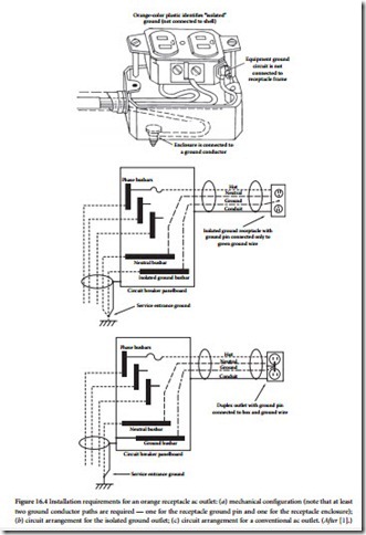
When appreciable inductance or resistance exists in an ac distribution system, the protection components located at the utility company service drop entrance (the primary suppressors) will carry most of the suppressed-surge current in the event of a lightning strike or major transient disturbance. The Orange-color plastic identifies “isolated” ground (not connected to shell)
varistors and RC networks downstream (the secondary and supplemental suppressors) are rated for clamp voltages lower than the primary protection devices. With the assistance of the ac circuit series resistance and impedance, the secondary and supplemental devices exercise tight control over voltage excursions.
The staged arrangement also protects the system from exposure caused by a transient-suppression device that — for whatever reason — becomes ineffective. The performance of an individual suppression component is more critical in a system that is protected at any one point than it is in a system protected at several points. The use of staged suppression also helps prevent transients generated by load equipment from being distributed to other sections of a facility, because suppressors can be located near offending machines.
Do not place transient suppressors of the same type in parallel to gain additional power-handling capability. Even suppressors that are identical in part number have specified tolerances; devices placed in parallel will not share the suppressed-surge current equally.
Design Cautions
Install transient suppressors at the utility service entrance with extreme care and only after consulting an experienced electrical contractor and the local utility company engineering department. Protection- device failure is rare, but it can occur, causing damage to the system unless the consequences of the failure are taken into account. Before installing a surge-limiting device, examine what would happen if the device failed in a short circuit (which is generally the case). Check for proper fusing on the protected lines, and locate transient-limiting devices in sealed enclosures to prevent damage to other equipment or injury to people if device failure occurs.
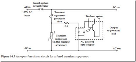
In the failure mode, current through the protection device typically is limited only by the applied volt- age and source impedance. High currents can cause the internal elements of the component to melt and to eventually result in an open circuit. However, high currents often cause the component package to rupture, expelling package material in both solid and gaseous forms. A transient suppressor must be fused if the line on which it is operating has a circuit-breaker (or fuse) rating beyond the point that would provide protection against package rupture of the suppressor. Selecting the fuse is a complicated procedure involving an analysis of the transient energy that must be suppressed, the rupture current rating of the suppressor, and the time-delay characteristics of the fuse. Transient-suppressor manufacturers can provide guidance on fuse selection. The monitoring circuit shown in Figure 16.7 can be used to alert maintenance personnel to an open fuse. Such provisions are important for continued safe operation of sensitive load equipment.
Lead length is another important factor to consider when installing transient-suppression components. Use heavy, solid wire (such as no. 12 AWG or larger of minimum length) to connect protection devices to the ac lines. Avoid sharp bends. If possible, maintain a minimum bending radius of 8 in. for interconnecting wires. Long leads act as inductors in the presence of high-frequency transients and as resistors when high-current surges are being clamped.
Give careful attention to proper heat-sink design when installing transient-suppression devices. Some suppressors require an external heat sink to meet their published specifications. If an adequate heat sink is not provided, the result may be premature device failure.
Specifications
Transient-suppression components fail when subjected to events beyond their peak current/energy ratings. They also can fail when operated at steady-state voltages beyond their recommended values. Examine the manufacturer’s product literature for each discrete protection device under consideration. Many companies have applications engineering departments that can assist in matching their product lines to specific requirements.
Consider using hybrid protection devices that provide increased product lifetime. For example, a varistor normally exhibits some leakage current. This leakage can lead to device heating and even- tual failure. Hybrid devices are available that com- bine a varistor with a gas-filled spark-gap device to hold the leakage current to zero during standby operation, extending the expected product lifetime. During a transient, the spark-gap fires and the varistor clamps the pulse in the normal way. Such a device is shown in Figure 16.8. Hybrid devices of this type are immune to power-follow problems discussed in Section 6.1.2.
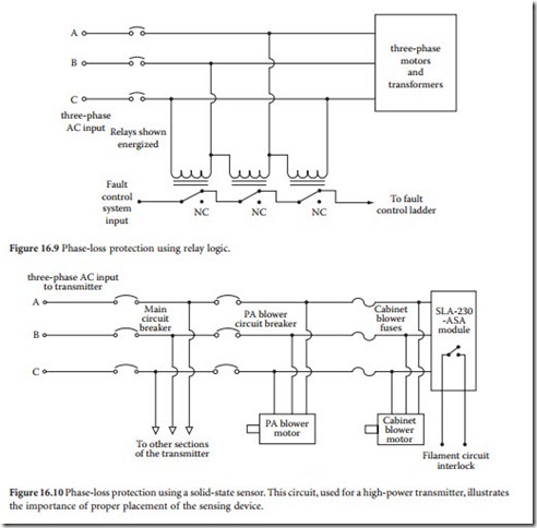
tribution system. Single-phasing is usually a utility company problem, caused by a downed line or a blown pole-mounted fuse. The loss of one leg of a three-phase line results in a particularly dangerous sit- uation for three-phase motors, which will overheat and sometimes fail. Figure 16.9 shows a simple protection scheme that has been used to protect industrial equipment from damage caused by single- phasing. At first glance, the system appears capable of easily handling the job, but operational problems can result.
The loss of one leg of a three-phase line rarely results in zero (or near-zero) voltages in the legs associated with the problem line. Instead, a combination of leakage currents caused by regeneration of the missing legs in inductive loads and the system load distribution usually results in voltages of some sort on the fault legs of the three-phase supply. It is possible, for example, to have phase-to-phase voltages of 220 V, 185 V, and 95 V on the legs of a three-phase, 208 Vac line experiencing a single-phasing problem. These voltages may change, depending upon what equipment is switched on at the facility.
Integrated circuit technology has provided a cost-effective solution to this common design problem. Phase-loss protection modules are available from several manufacturers that provide a contact closure when voltages of proper magnitude and phase are present on the monitored line. The relay contacts can be wired into the logic control ladder of the protected load to prevent the application of primary ac power during a single-phasing condition. Figure 16.10 shows the recommended connection method for a high-power transmitter. Note that the input to the phase monitor module is taken from the final set of three-phase blower motor fuses. In this way, any failure inside the system that might result in a single- phasing condition is taken into account. The phase-loss protector shown in the figure includes a sensitivity adjustment for various nominal line voltages. The unit is physically small and relatively inexpensive.
Protection against single-phasing is particularly important when transient-suppression devices are placed at the utility company service entrance. The action of suppressors can cause one or more of the fuses at the service drop transformer to open, creating a fault condition. Positive protection against con- tinued operation of the load under such circumstances is necessary to prevent equipment failure.
Surge Suppressor Selection
Surge suppressors and lightning arresters come in all shapes, sizes, and types; a complete discussion of application methods and evaluation is beyond the scope of this chapter. Contacting surge suppressor manufacturers, however, can be confusing because of the myriad of choices available. Instead, consider contacting members of referenced IEEE, Underwriters Laboratories (UL), and IEC standard committees
for help in understanding the application issues. In any event, the following general guidelines should be helpful [2]:
• Select suppressors and arresters based on IEEE C62.41 categories (A, B, or C).
• Check that the suppressors are UL 1449 tested, approved, and labeled.
• Ask for published proof of testing to back up claims, especially clamping levels, energy-handling capabilities (joules, watts, or current), and speed of response.
• Look for 3- to 5-year unconditional warranties on the products.
• Review and compare the six major performance characteristics: response time, voltage protection level, power dissipation, disturbance-free operation, reliability, and operating life. Make sure that the maximum power dissipation and voltage protection levels use specified waveforms and are stated at the same point to avoid misinterpretation.
• Talk to similar users for advice and recommendations.
• Consult industry standards for performance requirements.


