Introduction
To achieve high levels of power-system reliability — with the ultimate goal being 24-hour-per-day availability, 365 days per year — some form of power-system redundancy is required, regardless of how reliable the individual power-system components may be [1]. Redundancy, if properly implemented, also provides power-distribution flexibility. By providing more than one path for power flow to the load, the key elements of a system can be shifted from one device or branch to another as required for load balancing, system reno- vations or alterations, or equipment failure isolation. Redundancy also provides a level of fault tolerance. Fault tolerance can be divided into three basic categories:
• Rapid recovery from failures
• Protection against “slow” power system failures, where there is enough warning of the condition to allow intervention
• Protection against “fast” power system failures, where no warning of the power failure is given As with many corrective and preventive measures, the increasing costs must be weighed against the benefits.
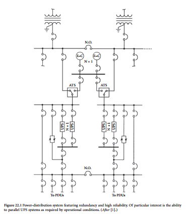
For example, recent developments in large UPS system technologies have provided the capability to operate two independent UPS systems in parallel, either momentarily or continuously. The ability to momentarily connect two UPS systems allows critical loads to be transferred from one UPS system to the other without placing the UPS systems in bypass, thereby maintaining continuous UPS protection of the loads. Continuous paralleling of the two UPS systems, on the other hand, can be used to create a single redundant UPS system from two otherwise nonredundant systems when multiple UPS modules are out of service (because of failures or maintenance). Figure 22.1 illustrates one such implementation.
Critical System Bus
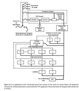
Many facilities do not require the operation of all equipment during a power outage. Rather than use one large standby power system, key pieces of equipment can be protected with small, dedicated, uninterruptible power systems. Small UPS units are available with built-in battery supplies for computer systems and other hardware. If cost prohibits the installation of a systemwide standby power supply (using generator or solid- state UPS technologies), consider establishing a critical load bus that is connected to a UPS system or generator via an automatic transfer switch. This separate power supply is used to provide ac to critical loads, thus keeping the protected systems up and running. The concept is illustrated in Figure 22.2. Unnecessary loads are dropped in the event of a power failure.
A standby system built on the critical load principle can be a cost-effective answer to the power-failure threat. The first step in implementing a critical load bus is to accurately determine the power requirements for the most important equipment. Typical power consumption figures can be found in most equipment instruction manuals. If the data is not listed or available from the manufacturer, it can be measured using a wattmeter.
When planning a critical load bus, be certain to identify accurately which loads are critical and which can be dropped in the event of a commercial power failure. If air-conditioning is interrupted but the
computer equipment at a large data processing center continues to run, temperatures will rise quickly to the point at which system components may be damaged or the hardware automatically shuts down. It may not be necessary to require cooling fans, chillers, and heat-exchange pumps to run without interruption. However, any outage should be less than 1 to 2 min in duration. Air-cooled computer systems can usually tolerate 5 to 10 min of cooling interruption.
Power-Distribution Options
There are essentially 12 building blocks that form what can be described as an assured, reliable, clean power source for computer systems, peripherals, and other critical loads [2]. They are:
• Utility and service entry (step-down transformer, main disconnect, and panelboard, switchboard, or switchgear)
• Lightning protection
• Power bus
• Facility power distribution
• Grounding
• Power conditioning equipment
• Critical load air-conditioning
• Frequency converter (if required)
• Batteries for dc backup power
• Emergency engine-generator
• Critical load power-distribution network
• Emergency readiness planning
A power system to support a critical load cannot be said to be reliable unless all these components are operating as intended, not only during normal operation, but especially during an emergency.
It is easy to become complacent during periods when everything is functioning properly, because this is the usual mode of operation. An absence of contingency plans for dealing with an emergency situation, and a lack of understanding of how the entire system works, thus, can lead to catastrophic shut- downs when an emergency situation arises. Proper training, and periodic reinforcing, is an essential component of a reliable system.
Plant Configuration
There are any number of hardware configurations that will provide redundancy and reliability for a critical load. Each situation is unique and requires an individual assessment of the options and — more importantly — the risks. The realities of economics dictate that cost is always a factor. Through proper design, however, the expense usually can be held within an acceptable range.
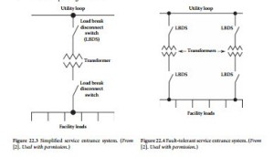
Design for reliability begins at the utility service entrance [2]. The common arrangement shown in Figure 22.3 is vulnerable to interruptions from faults at the transformer and associated switching devices in the circuit. Furthermore, service entrance maintenance would require a plant shutdown. In Figure 22.4, redundancy has been provided that will prevent the loss of power should one of the devices in the line fail. Because the two transformers are located in separate physical enclosures, maintenance can be performed on one leg without dropping power to the facility.
Of equal importance is the method of distributing power within a facility to achieve maximum reliability. This task is more difficult when dealing with a campus-type facility or a process or manufac- turing plant, where — instead of being concentrated in a single room or floor — the critical loads may be in a number of distant locations. Figure 22.5 illustrates power distribution through the facility using a simple radial system. An incoming line supplies the main and line feeders via a service entrance transformer. This system is suitable for a single building or a small process plant. It is simple, reliable, and lowest in cost. However, such a system must be shut down for routine maintenance, and it is vulnerable to single-point failure. Figure 22.6 illustrates a distributed and redundant power-distribution system that permits transferring loads as required to patch around a fault condition. This configuration also allows portions of the system to be de-energized for maintenance or upgrades without dropping the entire facility. Note the loop arrangement and associated switches that permit optimum flexibility during normal and fault operating conditions.


