Introduction
This chapter covers direct current (DC) tests ordinarily performed in the field for acceptance and maintenance of electrical equipment and apparatus. The information provided by these tests will indicate whether any corrective maintenance or replacement of installed equipment is necessary, assess if the newly installed equipment can be safely energized, and chart the gradual deterioration of the equipment over its service life.
The DC test methods discussed in this chapter cover transformers, insulating liquids, cables, switchgear, motors, and generators. It is important to have the proper equipment and trained operators when conducting these tests. Also, if any test is to provide optimum benefits, it is essential to record all test data and maintenance actions for further analysis and future reference. Furthermore, the test equipment should be maintained in good condition and used by qualified operators. When test equipment is used to calibrate other equipment, it should have twice the accuracy of the equipment under test. Moreover, the test equipment should be calibrated at regular intervals to assure the accuracy of test data.
The test voltage levels and methods, as described in this chapter, are mostly in accordance with industry standards for the types of equipment discussed. The DC voltage values correspond to the alternating current (AC) test volt- ages as specified by the applicable industry standards. It is recommended that the manufacturer of the equipment be consulted for specific test and test voltage levels when the exact construction of the equipment under test is not known. Where definitive information for a particular equipment cannot be obtained, it is advised that the suggested DC test voltage be based on the rated AC circuit voltage in order to avoid possible damage to the insulation system. It is also important to observe certain additional precautions when conducting DC high-voltage tests; these are listed in Section 2.11.
Electrical phenomena in insulation when subjected to DC voltage were briefly discussed in Chapter 1. Before discussing various DC voltage tests, we need to understand better the electrical phenomena in dielectrics when subjected to DC voltage, which are discussed in the following section.
DC Voltage Testing of Insulation
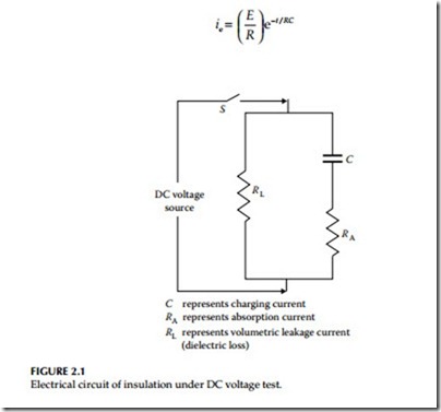
When DC voltage is applied to an insulation, the electric field stress gives rise to current conduction and electrical polarization. Consider an elementary circuit as shown in Figure 2.1, which shows a DC voltage source, a switch, and an insulation specimen. When the switch is closed, the insulation becomes electrified and a very high current flows at the instant the switch is closed. However, this current immediately drops in value, and then decreases at a slower rate until it reaches a nearly constant value. The current drawn by the insulation may be analyzed into several components as follows:
• Capacitance charging current
• Dielectric absorption current
• Surface leakage current
• Partial discharge current (corona)
• Volumetric leakage current
Capacitance charging current: The capacitance charging current is high as the DC voltage is applied and can be calculated by the formula
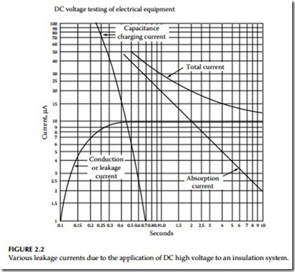
The charging current is a function of time and will decrease as the time of the application of voltage increases. It is the initial charging current when voltage is applied and therefore not of any value for test evaluation. Test readings should not be taken until this current has decreased to a sufficiently low value.
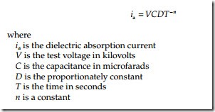
Dielectric absorption current: The dielectric absorption current is also high as the test voltage is applied and decreases as the voltage application time increases, but at a slower rate than the capacitance charging current. This current is not as high as the capacitance charging current. The absorption current can be divided into two currents called reversible and irreversible charging currents. This reversible charging current can be calculated by the formula:
The irreversible charging current is of the same general form as the revers- ible charging current, but is much smaller in magnitude. The irreversible charging current is lost in the insulation and thus is not recoverable. Again, sufficient time should be allowed before recording test data so that the revers- ible absorption current has decreased to a low value.
Surface leakage: The surface leakage current is due to the conduction on the surface of the insulation where the conductor emerges and points of ground potential. This current is not desired in the test results and should therefore be eliminated by carefully cleaning the surface of the conductor to elimi- nate the leakage paths, or should be captured and guarded out of the meter reading.
Partial discharge current: The partial discharge current, also known as corona current, is caused by overstressing of air at sharp corners of the conductor due to high test voltage. This current is not desirable and should be eliminated by the use of stress control shielding at such points during tests. This current does not occur at lower voltages (below 4000 volts), such as insulation resistance test voltages.
Volumetric leakage current: The volumetric leakage current that flows through the insulation volume itself is of primary importance. This is the current that is used to evaluate the conditions of the insulation system under test. Sufficient time should be allowed for the volumetric current to stabilize before test readings are recorded. The total current, consisting of various leakage currents as described above, is shown in Figure 2.2.
Dielectric Phenomena and Polarization
The dielectrics have the property of both temporary and permanent absorp- tion of electrical charges and property of conduction. When a voltage is applied to a dielectric, forces on the positive and negative charges inherent in the particles which make up the dielectric tend to orient the particles in line with the applied field. Some dielectric materials have molecules that have uneven number of atoms, that is, having asymmetrical arrangement of charges. When such a molecule is placed in an electrical field, it will migrate
in an electric field, thus become polarized with the electric field. Such a molecule is called a dipole. Dipoles play an important role in the electrical characteristics of the insulation. A dipole may be represented by a particle having small positive charge at one end and a small negative charge at the other end. When these dipoles are subjected to DC voltage, they are polar- ized and become aligned with respect to positive and negative polarity of the DC voltage. This phenomenon is known as dipole polarization. Polarization phenomenon is influenced strongly by the material properties, structure, and condition of the insulation.
On the other hand, charged particles, that is, particles with positive and negative charges, which are not interrupted by interfacial barriers, and can travel through the dielectric from one electrode to the other, constitute the leakage current, and are not part of the polarization phenomenon.
After a time when the applied voltage is removed from the dielectric, the polarized molecules will eventually revert to their initial random arrange- ment so that the polarization approaches zero. The time it takes for the polarization to drop to zero when the dielectric is short-circuited is known as relaxation time. It should be noted that the large dielectrics have a much longer relaxation time, and appropriate measures should be taken to dis- charge the released energy (voltage and current) to ground, which is given by the polarized molecules when they revert to their original state.
Advantages and Disadvantages of DC Voltage Testing
DC voltage testing is commonly used for testing of electrical equipment and apparatus. DC voltage testing has advantages and disadvantages which vary in importance with the specific circumstances. The advantages and disad- vantages of DC voltage are summarized below.
Advantages
• DC test is preferred on equipment whose charging capacitance is very high, such as cables.
• DC voltage stress is considered much less damaging to insulation than AC voltages.
• Time of voltage application is not as critical with DC voltage as with AC voltage.
• Test can be stopped before equipment failure occurs.
• Measurements can be taken concurrently.
• Historical data can be compiled and made available for evaluation.
• It is not necessary to make a separate insulation resistance test prior to making a DC overpotential test.
• Size and weight of equipment is significantly reduced compared to AC voltage test.
Disadvantages
• Stress distribution for transformers, motors, and generator winding is different for DC voltage than is for AC voltage.
• Residual charge after a DC voltage test must be carefully discharged.
• Time required to conduct a DC high-potential (hi-pot) test is longer than for an AC hi-pot test.
• Literature governing DC testing of cables suggest possible harmful effects hi-pot DC testing may have on some types of cables.
• Defects, undetectable with DC, can cause failure under AC voltage test.
• Voltage may not stress uniformly the insulation system.
• Temperature and voltage dependence of resistivity.
Space charge formation—future potential failures.


