Evaluation of Test Data Readings
Insulation resistance measurements, coupled with other information, can serve as a guide to determine what actions to take on electrical apparatus or cables. The choices are as follows:
• Place or restore the circuit to service until the next scheduled inspection.
• Restore the circuit to service now, but plan to perform indicated repairs as soon as possible.
• Leave out of service until repairs have been made.
What factors should be considered to determine whether insulation is good or bad?
• Rule of thumb: Minimum acceptable value of insulation to place equipment in service is 1 MΩ per rated kilovolt plus 1 MΩ. This is
based upon experience rather than the characteristics of insulation. The insulation resistance should never be less than 1 MΩ for all
equipment.
• Manufacturers’ information when available.
• Comparison with values obtained at acceptance or installation.
• Comparison with values from previous routine tests.
• Comparison with values of several similar units.
What physical factors may influence the readings?
• Contamination including dirt, moisture, acids, and salts.
• Contamination at terminal connection or at an end point can cause a low reading, and the true reading of a winding or cable will be unknown.
• Readings should be compared at a common temperature base, for example, 20°C. Different insulating materials have different tempera- ture correction tables, which are available in manufacturers’ literature.
2.10.1 Acceptance Criteria for Rating Insulation
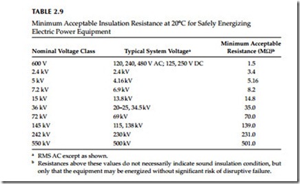
The minimum acceptable insulation resistance for safe energization of power equipment of each nominal voltage class is listed in Table 2.9. Values below these minimums indicate moisture, substantial thermal or chemical degra- dation, contamination, or physical damage. Equipment whose insulation resistance is less than the appropriate minimum is susceptible to disruptive failure and must not be energized for safety as well as economic reasons. Table 2.15 lists the insulation resistance values that are considered acceptable for healthy insulation. By examining the data given in Tables 2.9 and 2.15, the
difference should be obvious to the reader between what is considered a good value versus the absolute minimum value when evaluating the health of an insulation system.
An insulation resistance above the minimum in the table indicates only that the severely degraded conditions mentioned above do not exist and that the equipment may be energized safely. This does not necessarily mean that the insulation has acceptable dielectric strength, or that it is free of deterioration. A clean, dry insulation system in excellent condition should have a resistance several orders of magnitude larger than the mini- mum required for safe energization. For instance, the resistance of good 600 V class insulation is typically in the 100–1000 MΩ range.
In reality, the measured insulation resistance is of little significance on a one-time basis as long as it is well above the acceptance level. However, a long-term trend toward lower resistance strongly indicates progressive deterioration, which should be investigated and corrected.
To allow meaningful trending, the influence of irrelevant factors must be eliminated from the series of insulation resistance readings. The primary such factor is temperature. The measured resistance of a solid insulation system can change by as much two orders of magnitude as its temperature varies from the bottom to the top of the rated operating temperature range of the equipment. To eliminate this effect, tests whose results will be used for trending either should always be performed at essentially the same insulation temperature, or the results converted to a common temperature base.
Insulation testing and test trending procedures for equipment should be written accordingly.
In practice, the first alternative implies either testing the insulation when it is at nearly normal operating temperature, that is, as soon as possible after a period of normal, stable loading, or after the insulation has cooled to an ambient temperature, which is above the dew point and remains reasonably stable from test to test. In the second, more common approach, the resistances measured at varying temperatures are converted to a common standard temperature of 20°C using tables of empirically based correction factors given in the literature. Temperature coefficients of resistance vary greatly with the chemical composition of the insulation, so different corrections are required for different insulation systems. The equipment manufacturers’ literature is the best source of temperature correction information.
Humidity also affects the measured insulation resistance, but not nearly as much as temperature if the insulation system is reasonably clean.
In fact, large variations in insulation resistance with ambient humidity, in the absence of other explanations, indicate a possibility of contamination, which should be investigated. It is not normally necessary to correct for humidity effects.
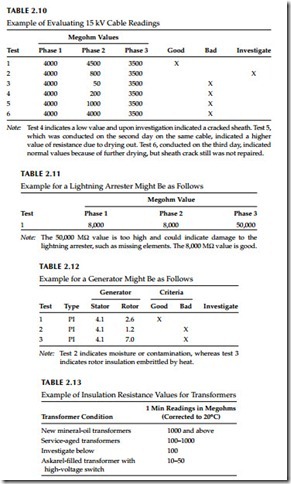
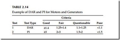
Tables 2.10 through 2.15 provide examples of rating insulation for various apparatus and equipment as to whether it is good, bad, or needs further investigation.


