Color Television
From the discussions of the trichromatic response of the eye and of the persistence of vision, it should be apparent that a color scene may be rendered by the quick successive presentation of the red, green, and blue components of a color picture. Provided that these images are displayed frequently enough, the impression of a full color scene is indeed gained. Identical reasoning led to the development of the first color television demonstrations by Baird in 1928 and the first public color television transmissions in America by CBS in 1951. Known as a field-sequential system, in essence the apparatus consisted of a high field-rate monochrome television system with optical red, green, and blue filters presented in front of the camera lens and the receiver screen, which, when synchronized together, produced a color picture. Such an electromechanical system was not only unreliable and cumbersome but also required three times the bandwidth of a monochrome system (because three fields had to be reproduced in the period previously taken by one). In fact, even with the high field rate adopted by CBS, the system suffered from color flicker on saturated colors and was soon abandoned after transmissions started. Undeterred, the engineers took the next most obvious logical step for producing colored images. They argued that instead of presenting sequential fields of primary colors, they would present sequential dots of each primary. Such a (dot sequential) system using the secondary primaries of yellow, magenta, cyan, and black forms the basis of color printing. In a television system, individual phosphor dots of red, green, and blue, provided they are displayed with sufficient spatial frequency, provide the impression of a color image when viewed from a suitable distance.
Consider the video signal designed to excite such a dot-sequential tube face. When a monochrome scene is being displayed, the television signal does not differ from its black and white counterpart. Each pixel (of red, green, and blue) is equally excited, depending on the overall luminosity (or luminance) of a region of the screen. Only when a color is reproduced does the signal start to manifest a high-frequency component, related to the spatial frequency of the phosphor it is designed successively to stimulate. The exact phase of the high-frequency component depends, of course, on which phosphors are to be stimulated. The more saturated the color (i.e., the more it departs from gray), the more high-frequency “colorizing” signal is added. This signal is mathematically identical to a black and white television signal whereupon a high-frequency color-information carrier- signal (now known as a color subcarrier) is superimposed—a single frequency carrier whose instantaneous value of amplitude and phase, respectively, determines the saturation and hue of any particular region of the picture. This is the essence of the NTSC1 color television system launched in the United States in 1953, although, for practical reasons, the engineers eventually resorted to an electronic dot-sequential signal rather than achieving this in the action of the tube. This technique is considered next.
NTSC and PAL Color Systems
If you’ve ever had to match the color of a cotton thread or wool, you’ll know you have to wind a length of it around a piece of card before you are in a position to judge the color. That’s because the eye is relatively insensitive to colored detail. This is obviously a phenomenon of great relevance to any application of color picture reproduction and coding; that color information may be relatively coarse in comparison with luminance information. Artists have known this for thousands of years. From cave paintings to modern animation studios it is possible to see examples of skilled, detailed monochrome drawings being colored in later by a less skilled hand.
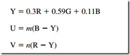
The first step in the electronic coding of an NTSC color picture is color-space conversion into a form where brightness information (luminance) is separate from color information (chrominance) so that the latter can be used to control the high-frequency color subcarrier. This axis transformation is usually referred to as RGB to YUV conversion and it is achieved by mathematical manipulation of the form:
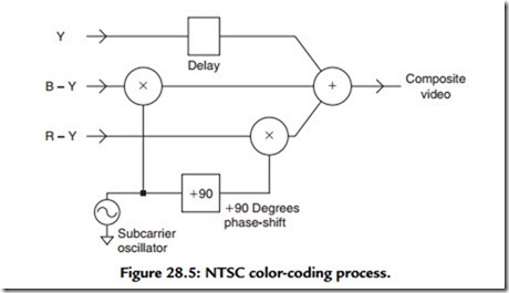
The Y (traditional symbol for luminance) signal is generated in this way so that it as nearly as possible matches the monochrome signal from a black and white camera scanning the same scene. (The color green is a more luminous color than either red or blue and red is more luminous than blue.) Of the other two signals, U is generated by subtracting Y from B: for a black and white signal this evidently remains zero for any shade of gray. The same is true of R – Y. These signals therefore denote the amount the color signal differs from its black and white counterpart. They are therefore dubbed color difference signals. (Each color difference signal is scaled by a constant.) These signals may be a much lower bandwidth than the luminance signal because they carry color information only, to which the eye is relatively insensitive. Once derived, they are low-pass filtered to a bandwidth of 0.5 MHz.2 These two signals are used to control the amplitude and phase of a high-frequency subcarrier superimposed onto the luminance signal. This chrominance modulation process is implemented with two balanced modulators in an amplitude-modulation-suppressed-carrier configuration—a process that can be thought of as multiplication. A clever technique is employed so that U modulates one carrier signal and V modulates another carrier of identical frequency but phase shifted with respect to the other by 90°. These two carriers are then combined and result in a subcarrier signal that varies its phase and amplitude dependent on the instantaneous value of U and V. Note the similarity between this and the form of color information noted in connection with the dot-sequential system: amplitude of high-frequency carrier dependent on the depth—or saturation—of the color and phase dependent on the hue of the color. (The difference is that in NTSC, the color subcarrier signal is coded and decoded using electronic multiplexing and demultiplexing of YUV signals rather than the spatial multiplexing of RGB components attempted in dot-sequential systems.) Figure 28.5 illustrates the chrominance coding process.
While this simple coding technique works well, it suffers from a number of important drawbacks. One serious implication is that if the high-frequency color subcarrier is attenuated (for instance, due to the low pass action of a long coaxial cable), there is a
resulting loss of color saturation. More serious still, if the phase of the signal suffers from progressive phase disturbance, the color in the reproduced color is likely to change. This remains a problem with NTSC where no means are taken to ameliorate the effects of such a disturbance. The phase alternation line (PAL) system takes steps to prevent phase distortion having such a disastrous effect by switching the phase of the V subcarrier on alternate lines. This really involves very little extra circuitry within the coder but has design ramifications, which means the design of PAL decoding is a very complicated subject indeed. The idea behind this modification to the NTSC system (for that is all PAL is) is that, should the picture—for argument’s sake—take on a red tinge on one line, it is cancelled out on the next when it takes on a complementary blue tinge. The viewer, seeing this from a distance, just continues to see an undisturbed color picture. In fact, things aren’t quite that simple in practice but the concept was important enough to be worth naming the entire system after this one notion: phase alternation line. Another disadvantage of the coding process illustrated in Figure 28.5 is because of the contamination of luminance information with chrominance and vice versa. Although this can be limited to some degree by complementary band-pass and band- stop filtering, a complete separation is not possible, which results in the swathes of moving colored bands (cross-color), which appear across high-frequency picture detail on television—herringbone jackets proving especially potent in eliciting this system pathology.
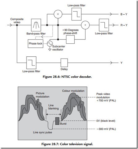
In the color receiver, synchronous demodulation is used to decode the color subcarrier. One local oscillator is used and the output is phase shifted to produce the two orthogonal carrier signals for the synchronous demodulators (multipliers). Figure 28.6 illustrates the block schematic of an NTSC color decoder. A PAL decoder is much more complicated.
Mathematically, we can consider the PAL and NTSC coding process, thus
Note that following the demodulators, the U and V signals are low-pass filtered to remove the twice frequency component and that the Y signal is delayed to match the processing delay of the demodulation process before being combined with the U and V signals in a reverse color space conversion. In demodulating the color subcarrier, the regenerated carriers must not only remain spot-on frequency, but also maintain a precise phase
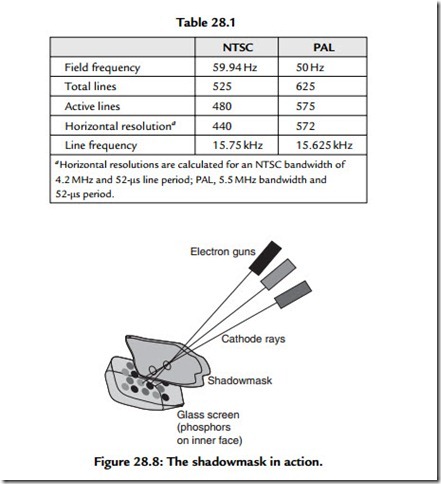
relationship with the incoming signal. For these reasons the local oscillator must be phase locked and for this to happen the oscillator must obviously be fed a reference signal on a regular and frequent basis. This requirement is fulfilled by the color burst waveform, which is shown in the composite color television signal displayed in Figure 28.7.
The reference color burst is included on every active TV line at a point in the original black and white signal given over to line retrace. Note also the high-frequency color information superimposed on the “black and white” luminance information. Once the demodulated signals have been through a reverse color space conversion and become RGB signals once more, they are applied to the guns of the color tube (Table 28.1).
As you watch television, three colors are being scanned simultaneously by three parallel electron beams, emitted by three cathodes at the base of the tube and all scanned by a common magnetic deflection system. But how to ensure that each electron gun only
excites its appropriate phosphor? The answer is the shadowmask—a perforated, sheet- steel barrier that masks the phosphors from the action of an inappropriate electron gun. The arrangement is illustrated in Figure 28.8. For a color tube to produce an acceptable picture at reasonable viewing distance, there are about half a million phosphor red, green, and blue triads on the inner surface of the screen. The electron guns are set at a small angle to each other and aimed so that they converge at the shadowmask. The beams then pass through one hole and diverge a little between the shadowmask and the screen so that each strikes only its corresponding phosphor. Waste of power is one of the very real drawbacks of the shadowmask color tube. Only about a quarter of the energy in each electron beam reaches the phosphors. Up to 75% of the electrons do nothing but heat up the steel!
