FORD DUAL CARBURETOR OVERHAUL
Disassemble
To facilitate working on the carburetor and to avoid damage to the throttle plates, use bolts through the carburetor retaining stud holes with a nut above and below th e flange. Be sure that the bol t diam eter and thread size match the hole diameter. Bolt length should be approximately 2W’.
Air Horn
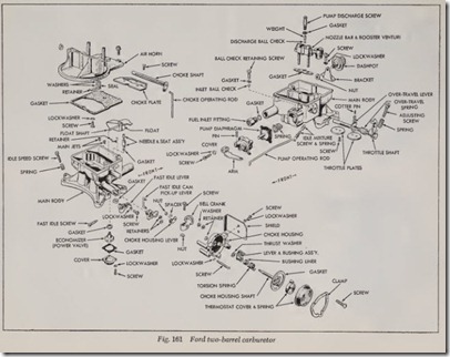
1. Referring to Fig. 161, remove air cleaner anchor stud. Discom1ect choke plate operating rod at choke housing lever by loosening set screw. ,
2. Remove retaining screws and remove air hom and gasket.
3. Remove hairpin retainer that attaches choke operating rod to choke shaft lever. Remove rod.
4. Slide choke rod felt seal and two washers from between retainer and air hom.
5. If seal retainer bracket is damaged, remove it by driving out the retaining rivet.
6. If choke plate or shaft is damaged, file off peened end of choke plate retaining screws and remove screws, plate and shaft.
Main Body
1. Remove fuel inlet fitting and gasket.
2. Use a hook and disconnect float shaft retainer.
Then remove float and shaft, and fuel inlet needle and clip.
3. Remove fuel inlet needle seat, gasket, and float shaft retainer, and remove main jets .
4. Remove booster venturi attaching screw gasket, then lift nozzle bar and booster venturi assembly and gasket out of main body.
5. Invert main body and let acceleratin g pump discharge ball and weight fall into your h and.
6. Invert main body and remove power valve cover and gasket, then remove power valve and gasket.
7. Remove accelerating pump operating rod, then remove pump cover, diaphragm and spring. To release the clip, it is necessary to press on the tab portion of the clip while with drawing the rod. Do not pry clip from rod.
8. Remove acclerating pump inlet ball check retainer screw and gasket. Remove ball check.
9. Remove choke shield.
10. Disconnect fast idle cam pickup lever at fast idle cam.
11. Remove thermostatic coil housing retaining screws and clamp, then remove housing and gasket.
12. Remove choke housing and gasket.
13. Remove choke housing lever attaching nut, spacer and lever. Loosen screw on bellcrank clamp and slide bellcrank off choke housing shaft and lever assembly. Remove fast idle cam rod.
14. Remove retainer from choke housing shaft and lever and slide shaft out of choke housing .
15. Slide therll1ostatic coil lever and bushing off choke housing shaft, taking care to allow for the twisting action of the torsion spring when the parts are separated. Remove torsion spring and sleeve bearing from thermostatic coil lever and bu sh ng.
16. Remove f ast idle cam retainer and slide fast
idle cam off boss on main body.
17. Remove nut and washer securing fast idle ad ju sting lever to throttle shaft and slide lever off shaft.
18. Remove distributor vacuum line fitting, the anti-stall dashpot (if equipped), idle fuel ad j usting needles, and idle speed adjusting screw and spring.
19. If it is necessary to remove throttle plates,
lightly scribe both plates along throttle shaft and mark each plat e and corresponding bore with a number or letter: for proper installation.
20. Remove throttle plate screws and plates, then
slide throttle shaft out of body .
21. Remove accelerating pump overtravel lever ret ainer. Slide overtravel spring and lever off shaf t .
Assembly
Make sure all holes in the new gaskets have been properly punched and th at no foreign ma terial has adhered to them . Mak e sure also that the accelerating pump diaphragm is not torn or cut. Refer to Fig. 161 while performing the follow ing operations.
Air Horn
1. Position chok e shaft and plate in air horn.
2. Close choke plate to position it in shaft, then install and tighten screws . Stake screws with duck bill pliers or other suitable staking tool.
3. If choke seal retainer was removed, enlarge rivet hole with a No. 28 drill ( .140″ dia.) and thread the hole with a No. 8-32 tap. Secure seal retainer with a No. 8-32 screw.
4. Position rod seal between the two brass wash ers and slide them into position between re tainer and air horn.
5. Install choke operating rod and hairpin type retainer.
Main Body
1. If throttle plates were removed , place the ac celerating pump overtravel spring, with short est tang end first, over boss on pump over travel lever. Place short tang of spring under lug on lever.
2. Slide overtravel lever and spring, spring end
first, on throttle shaft.
3. Hook longest tang of spring over throttle lug of throttle lever and install pump overtravel lever retainer.
4. Slide throttle shaft into main body.
5. Referring to line scribed on throttle plates during disassembly, install plates in their proper location with th e screws just snug (not tight). Hold throttle plates closed and hold main body up to light. Little or no light should show between throttl e plates and throttle bores. Tap plates lightly with a screwdriver handle to seat them, then tighten the screws. Stake screws with duck bill pliers or other suitable staking tool.
6. Install idle speed screw and spring.
7. Position anti-stall dashpot.
8. Install distributor vacuum passage fitting.
9. Place fast idle adjusting lever on throttle shaft and install washer and nut.
10. Slide fast idle cam on boss of main body and install retainer.
11. Install white sleeve bearing and torsion spring on thermostat lever and bushing. Rolling sleeve bearing around itself will assist it in maintaining conformity around brass bushing.
12. Slide thermostat lever, bushing and torsion spring on choke housing shaft and engage spring.
13. Install complete choke housing shaft and lever in choke housing so that thermostat lever is at top of choke housing. Install choke housing shaft retainer.
14. Install bellcrank on choke housing shaft and position it so that lever is against shaft retainer and the slot portion is to the front of choke housing, Fig. 162. (Refer to “Adjust ments.”)
15. Install fast idle cam pickup rod on bellcrank.
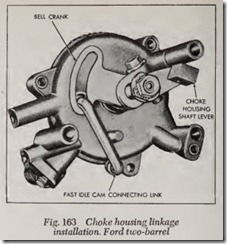
16. Position choke housing lever on choke housing shaft and install spacer, washer and nut, Fig. 163.
17. Place new choke housing gasket on main body.
Position choke housing on main body, en gaging fast idle cam pickup lever in hole in fast idle cam.
18. Install choke housing and screws.
19. Position thermostatic spring housing gasket and housing on choke housing and align index mark on spring housing with middle index mark on choke housing.
20. Install clamp screws, and choke shield.
21. Drop accelerating pump inlet ball in fuel inlet passage of the pump chamber and install washer and retaining screw.
22. Install the diaphragm return spring on the boss in the chamber. Insert the diaphragm as sembly in the cover and place the cover and diaphragm assembly in position on the main body.
23. Install the cover screws finger tight, then push the accelerating pump plunger the full dis tance of its travel and tighten the cover screws.
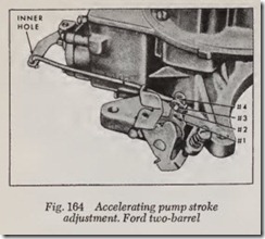
24. Position the accelerator pump operating rod in the inner hole of the link arm of the ac celerator pump. Install the other end of the rod in the No. 3 hole (third hole from the throttle shaft). This position is for average and warm temperature operation. If necessary, the rod may be installed in the No.4 hole position (farthest from throttle shaft for cold weather operation. The No. 1 and No. 2 hole positions may be used for unusually hot operating con ditions.
25. Invert the main body and install the power valve and gasket, then install the cover and gasket.
26. Install the idle adjusting needles and springs.
Turn the needles in gently with the fingers until they fust touch the seat, then back them off n turns for a preliminary idle adjustment.
27. Insert the main jets.
28. Position the float shaft retainer in the groove on the fuel inlet needle seat, then install the seat and gasket.
29. Slide the float shaft in the float lever.
30. Install the fuel inlet needle clip in the groove on the fuel inlet needle and hook the assembly on the float tab.
ADJUSTMENTS
Accelerator Pump Stroke
Fig. 164. Install pump operating rod in the inner hole of the pump operating link. The other end of the pump rod should be installed in the third hole of the overtravellever from the throttle shaft for average weather conditions. The fourth or outer hole is for extreme cold weather opera tion. The first and second holes are for any re quired variations from the standard positions.
Anti-Stall Dashpot
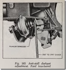
Fig. 165. To adjust the dashpot operating clear ance, adjust the engine idle speed.
Hold the throttle in the closed position, and then, fully depress the dashpot plunger stem using a thin blade screwdriver.
Check the available clearance between the plunger tip and the throttle lever (or the dashpot operating lever on a single-barrel carburetor).
To adjust the clearance on all eight cylinder carburetors, loosen the locknut and rotate the dashpot in a direction to provide .060-.090 inch clearance. Tighten the locknut to secure the ad justment.
To adjust the clearance on the six cylinder carburetor, loosen the locknut and rotate the dashpot in a direction to provide .120-150 inch clearance.
Automatic Choke Adjustment
The normal setting for the thermostatic housing is two marks lean. The final setting may be varied but not to exceed two marks from the normal setting.
the spring to correct for leanness or richness in the automatic choke during drive-away, immediately after a cold start.
If there is an apparent leanness in the carburetor during drive-away after a cold start in low ambient temperatures, tension of the choke hous ing spring should be increased by moving the tang of the spring from the center finger to the finger that is to the left of the center position.
If there is an apparent richness and tendency to load-up during drive-away after a cold start in low ambient temperatures, the tension of the choke housing spring should be decreased by moving the tang of the spring from the center finger to the finger that is to the right of the center position.
Initial Choke Plate Pull-Down Setting
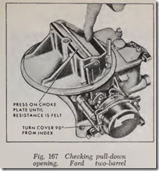
1. Turn the choke coil housing 90 degrees counter clockwise to assure positioning of the choke linkage in the fully closed choke position, Fig. 167.
2. Press the choke plate toward the open position until resistance to movement is felt.
CAUTION: Do not use force or the tang on the lever in the choke housing will be bent or broken.
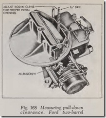
3. Measure the clearance between the lower edge of the choke plate and the inside vertical sur face of the air horn. The clearance should be 7/64 inch. To adjust the clearance, loosen the set screw on the choke plate operating lever clevis with a 1/16 inch Allen wrench, and move the choke plate oprating rod up or down with in the clevis until a clearance is achieved, Fig. 168.
4. Recheck the fast idle cam to choke housing clearance and adjust it, if necessary. (This clearance should be 0.050 inch.)
5. Reset the choke coil housing to the specified setting.
Float Level
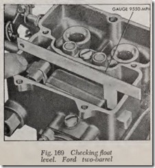
Hold the float in the uppermost position by pressing downward on the float tab. Place Gauge 9550-MFB on the bowl lengthwise to the Boat.
The gauge should just contact the Boat. Position the gauge as shown in Fig. 169.
