Objectives
After studying this unit, the student will be able to:
• Discuss different methods of changing the speed of ac induction motors
• Discuss how an alternator is used to provide variable frequency motor control
• Discuss electronic methods of variable frequency control
Two factors determine the speed of the rotat ing magnetic field of an ac induction motor:
1. Number of stator poles
2. Frequency
If either of these factors is changed, the speed of the motor can be changed.
In Unit 52, the operation of the consequent pole motor was discussed. The speed of the con sequent pole motor can be changed by changing the number of stator poles. This method of speed control causes the speed to change in steps and does not permit control over a wide range of speed. For example, the synchronous speed of the rotating magnetic field in a two-pole motor is 3600 rpm when connected to a 60 Hz line. If this motor is changed to a four-pole motor, the synchronous speed will change to 1800 rpm. Notice that this method of speed control permits the motor to op erate with a synchronous field speed of 3600 rpm or 1800 rpm. The motor cannot be operated with a synchronous speed between 3600 rpm and 1800 rpm.
VARIABLE VOLTAGE SPEED CONTROL
Another method of controlling the speed of some ac induction motors is by reducing the ap plied voltage to the stator. This method does not change the synchronous speed of the rotating mag netic field, but it does cause the magnetic field of the stator to become weaker. As the magnetic field of the stator becomes weaker, the rotor slip be comes greater and, therefore, causes a reduction in rotor speed.
Variable voltage speed control is used with fractional horsepower motors that operate light loads such as fans or blowers. Motors that are in tended to be operated with variable voltage are de signed with high resistance rotors, such as the type “A” rotor, to help limit the amount of cur rent induced into the rotor at low speed. Induc tion motors that use a centrifugal switch cannot be used with variable voltage control. This limits the types of induction motors that can be used to shaded pole motors or capacitor start-capacitor run motors.
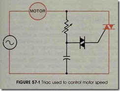
There are several methods used to control the voltage supplied to the motor. One method is to use a triac with a phase shift network similar to the circuit shown in figure 57-1. When triac cir cuits are used with inductive loads, care must be taken to insure that both halves of the ac wave form are conducted. Only triac controllers in tended to be used with inductive loads should be used for motor control. Triac circuits intended to control incandescent lamp loads will often begin conducting on one half of the ac cycle and not the other. For example, assume the triac in figure 57-1 begins conducting on the positive half cycle of voltage before it conducts the negative half cy cle. A waveform similar to the one shown in figure 57-2 could be produced across the load. Since only positive voltage pulses are being conducted, the voltage applied to the load is de. A de voltage ap plied to a resistive load such as an incandescent lamp will not cause any harm, but a great deal of harm can be done if a de voltage is applied to an inductive load such as the stator winding of a mo tor. A variable speed control using a triac is shown in figure 57-3.
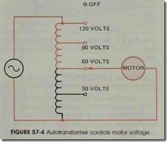
Another device used to control the voltage ap plied to a small induction motor is the autotrans former, figure 57-4. In this circuit, a rotary switch is used to connect the motor to different taps on the transformer winding. This permits the motor to be operated at any one of several different speeds.
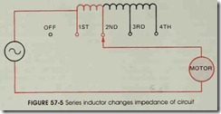
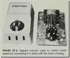
A tapped inductor can also be used to control motor speed, figures 57-5 and 57-6. In this circuit, the inductor is not used to control the voltage ap plied to the motor, but is used to control the impedance of the circuit. If more of the inductor is connected in series with the motor, the total impedance of the circuit is increased and, there fore, the current flow through the motor is de creased. As current flow is decreased, the mag netic field of the stator becomes weaker and the increase in rotor slip causes the motor speed to slow down . The motor speed can be adjusted by changing the tap with the rotary switch to insert more or less of the inductor winding in series with the motor.
VARIABLE FREQUENCY CONTROL
One of the factors that determines the speed of the rotating magnetic field of an induction mo tor is the frequency of the applied voltage. If the frequency is changed, the speed of the rotating magnetic field changes also. For example, a four pole stator connected to a 60 Hz line will have a synchronous speed of 1800 rpm. If the frequency is lowered to 30 Hz, the synchronous field speed falls to 900 rpm.
When the frequency is lowered, care must be taken not to damage the stator winding. The cur rent flow through the winding is limited to a great extent by inductive reactance. When the fre quency is lowered, inductive reactance is lowered also (XL = 27rFL). For this reason, variable fre quency motor controllers must have some method of reducing the applied voltage to the stator as fre quency is reduced.
Alternator Control
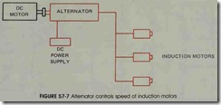
One method of producing variable frequen cies for operating induction motors is with the use of an alternator, figure 57-7. In this arrangement some type of variable speed drive, such as demo tor, is used to turn the shaft of the alternator. The speed of the alternator determines the frequency of the voltage applied to the induction motors. The alternator can furnish power to as many in duction motors as desired provided the power rat ing of the alternator is not exceeded.
Since the output voltage of the alternator is controlled by the amount of de excitation current applied to the rotor, a variable voltage de power supply is used to determine the output voltage of the alternator. As frequency is reduced, the out put voltage must also be reduced to prevent exces sive current flow in the windings of the induction motors. This method of speed control is fre quently used on conveyor systems where it is de sirable to have a large number of motors con trolled from one source.
Solid-State Control
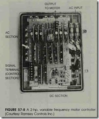
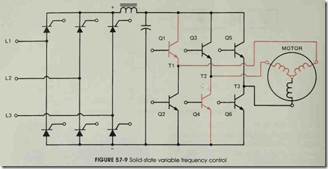
Most solid-state variable frequency drives op erate by first changing the ac voltage to de, and then changing the de voltage back to ac at the de sired frequency. A variable frequency controller is shown in figure 57-8. The circuit shown in figure 57-9 uses a three-phase bridge rectifier to convert three-phase ac voltage into de voltage. A phase shift unit controls the output voltage of the recti fier. This permits the voltage applied to the motor to be decreased as the frequency is decreased.
A choke coil and capacitor bank are used to filter the output voltage of the rectifier before tran sistors Ql through Q6 change the de voltage back to ac. An electronic control unit is connected to the bases of transistors Ql through Q6. The elec tronic control unit converts the de voltage back into three-phase alternating current by turning transistors on or off at the proper time and in the proper sequence. For example, assume that tran sistors Ql and Q4 are switched on at the same time. This permits Tl to be positive at the same time T2 is negative. If conventional current flow is assumed, current will flow through transistor Ql to Tl, from Tl through the motor winding to T2, and then through transistor Q4 to negative. Now assume that transistors Ql and Q4 have been turned off, and transistors Q3 and Q6 have been turned on. Current can now flow through transis tor Q3 to T2, from T2 through the motor to T3, and through transistor Q6 to negative.
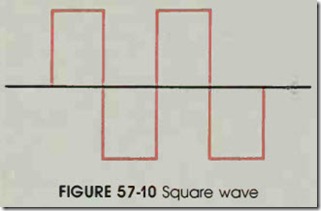
Since the transistors are turned completely on or completely off, the waveform produced is a square wave instead of a sine wave, figure 57- 10.
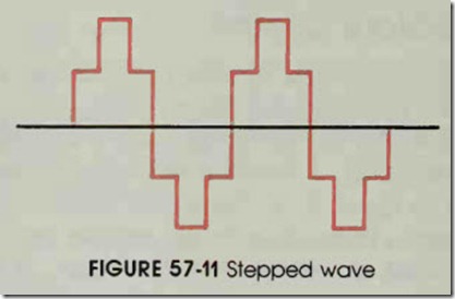
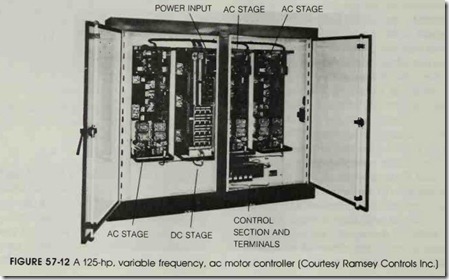
Induction motors will operate on a square wave form without any problem. Some manufacturers design units that will produce a stepped waveform as shown in figure 57-11. This stepped waveform is used because it is similar to a sine wave. An other type of variable frequency ac motor control ler is shown in figure 57-12.
VARIABLE FREQUENCY CONTROL
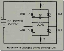
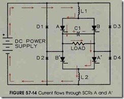
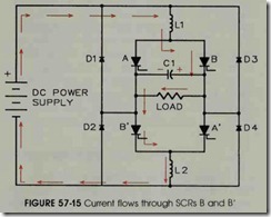
Because of their ability to handle large amounts of power, SCRs are often used for con verting direct current into alternating current. An example of this type of circuit is shown in figure 57-13. In this circuit, the SCRs are connected to a control unit which controls the sequence and rate at which the SCRs are gated on. The circuit is constructed so that SCRs A and A’ are gated on at the same time and SCRs B and B’ are gated on at the same time. Inductors L1 and L2 are used for filtering and wave shaping. Diodes D1 through D4 are clamping diodes and are used to prevent the output voltage from becoming excessive. Capaci tor C1 is used to turn one set of SCRs off when the other set is gated on. This capacitor must be a true ac capacitor because it will be charged to the alternate polarity each half cycle. In a converter intended to handle large amounts of power, capac itor C1 will be a bank of capacitors. To understand the operation of this circuit, assume that SCRs A and A’ are gated on at the same time. Current will flow through the circuit as shown in figure 57-14. Notice the direction of current flow through the load and that capacitor cl has been charged to the polarity shown. Recall that when an SCR has been turned on by the gate, it can only be turned off by permitting the current flow through the anode cathode section to drop below the holding current level. Now assume that SCRs B and B’ are gated on. Because SCRs A and A’ are still turned on, two separate current paths now exist through the circuit. The negative charge on capacitor C > how ever, causes the positive current to see a path more n gative than the one through SCRs A and A’. The current now flows through SCRs B and B’ to charge capacitor C1 to the opposite polarity as shown in figure 57-15. Because the current now flows through SCRs B and B’, SCRs A and A’ turn off. Notice that the current flows through the load in the opposite direction, which produces alternating current through the load, and that
capacitor cl has been charged to the opposite polarity.
To produce the next half cycle of ac current, SCRs A and A’ are gated on again. The negatively charged side of capacitor C1 will now cause the current to stop flowing through SCRs B and B’ and begin flowing through SCRs A and A’ as shown in figure 57-14. The frequency of the cir cuit is determined by the rate at which the SCRs are gated on.
REVIEW QUESTIONS
1. What two factors determine the synchronous speed of the rotating magnetic field of an induction motor?
2. What method of speed control that is often used with small motors does not involve changing the speed of the rotating magnetic field?
3. Name two devices commonly used to control the voltage applied to the motor.
4. Name the two types of motors most often used when speed control is accomplished by reducing the voltage applied to the motor.
5. Why are these two motors generally used for this type of speed control?
6. What type of rotor is generally used with motors designed to be controlled by variable voltage?
7. What determines the output frequency of an alternator?
8. What determines the output voltage of an alternator?
9. In the circuit shown in figure 57-9, why are SCRs used to form the three phase bridge rectifier instead of diodes?
10. Why must the voltage applied to an induction motor be reduced when frequency is reduced?
