Guidelines for Effective motor installation
Here are latest techniques for installation, connecting, and startup of modern motors-covering location, mounting, couplings, terminations, testing, and NEC rules.
By ROBERT J. LAWRIE, Associate Editor
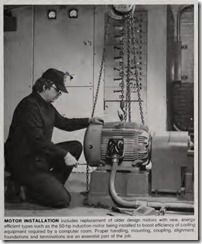
PROPER installation of an electric motor is essential to obtain top quality operation, efficient perform ance, and maximum reliability. For a totally cost-effective installation, pro cedures shou ld consider all aspects of engineering, design, selection, applica tion, and maintenance as well as the details of assembly, hardware , and interrelationship of components and materials. The work demands close coordination, planning, and teamwork on the part of the engineers, installers,and those responsible for maintenance; and completion of a successful motor installation requires that the latest and best construction techniques be em ployed.
Receiving and handling
When a motor is received, it should be thoroughly inspected for scratches, dents, or other signs of damage. This inspection should be done before the motor is moved from the shipper’s truck or other vehicle. Examine all literature provided with the motor. Do not remove tags pertaining to assem bly, storage, lubrication and operation. File all literature with specifications and drawings pertaining to the motor for reference during installation and for guidance during startup and opera tion.
Handling of large, heavy motors should be supervised by qualified rig gers with experience in the use of cranes, hoists, jacks, rollers, wire ropes, cables, hooks, slings and other equipment that may be needed.
Always check the motor nameplate for proper voltage, phase, frequency, horsepower, etc. Large motors are sometimes shipped disassembled. When assembling, be sure all mating parts are clean. Cleaning can be done with a magnet, vacuum cleaner, or dry compressed air (air pressure less than 60 psi).
On smaller motors, turn the shaft by hand to be sure that it turns freely. If the motor is equipped with antifriction bearings, they will normally be prelub ricated and ready for operation. How ever, large motors having sleeve bear ings are usually shipped without lubri cating oil in the bearings; often they are filled with an antirust fluid. Bearings should be inspected through the sight-glass and bearing-drain openings for any accumulations of moisture and traces of oxidation. Then, fill the bear ing reservoirs to normal level with a high-grade industrial lubricating oil.
Safety procedures
Safety is of paramount importance during the installation, startup and operation of motors. Safety starts with proper design, application and selection of the motor and associated compo nents. Be sure that the motor has been well matched to handle the type of load to be driven. Be certain that the enclo sure is suited to the surrounding envi ronment and that there is adequate ventilation to assure operation at or below motor design temperature. Check that the motor, gears, belts, driven machinery, etc. are guarded so that anyone near the installation will not be harmed by accidental contact.
All personnel involved with the installation should be familiar with NEMA MG2, Safety Standards for Construction and Guide for Selection, Installation and Use of Electric Mo tors and Generators. Pertinent NEC rules, especially Ar icle 430, and all local safety rules must be observed. In addition, OSHA rules must be studied and followed during the installation of motors and controls. These regulations are included in Part 1910 of the Occu pational Safety and Health Standards. Obtain a copy of this document from any local OSHA office.
Location considerations
An open-type motor is usually the best choice for installation in surroundings reasonably free of moisture, dust or lint. Be sure space is available for maintenance or replacement. Open motors having commutators or collec tor rings must be located or protected so that sparks cannot reach adjacent combustible material. This does not preclude the mounting of such motors on wooden platforms or floors.
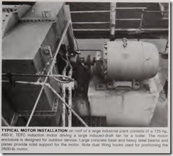
Dripproof motors are intended for use where the atmosphere is relatively clean, dry and noncorrosive. Keep windings clean with a soft brush, cloth or suction. Totally enclosed motors may be installed where dirt, moisture and corrosion are present, or in out door locations. If a drain plug is pro vided in the end bracket or bell, it should be removed periodically to drain any accumulated condensation. The motor should be installed to deliver adequate power safely. Temperature rise of a standard motor is based on operation at an altitude not higher than 3300 ft above sea level.
When unusual environment s or con ditions exist (high temperatur es, ex treme vibration, etc.), special enclo sures or arrangements must be incor porated into the installation .
Alwa ys try to locate the motor in th e best possible environment-a clean, dry, cool location. Often, electrical equipment rooms are specially con structed so that motors and other equipment will operate in a suitable environment and obtain long lif e and simplified maintenance. How eve r, many motor enclosures are available that will permit operation in a vari ety of environments. The specific applica tion and the nature of any contami nants present will dictate th e be st enclosure for the job.
Moisture problems requir e special consideration. Suitable guard s or en closures must be provided to protect exposed current-carrying parts of mo tors and the insulation of motor leads where dripping or spraying oil, water, or other injurious liquid may occur, un less the motor is specially d esign ed for the existing conditions .
In addition to open (gen eral-purpose), dripproof , and totally enclosed fan cooled (TEFC), a number of oth er designs are available for specific envi ronments and applications. For standy service or for damp-location operation, a low single-phase voltage (on t h e order of 5 to 10% of rated voltage) i s sometimes applied to the windin gs to combat moisture . Some larger motors are available with built-in strip- or tubular -type space heater s f or this purpose.
Foundations
A rigid foundation is essential for minimum vibration and proper align ment between motor and load. Concrete, reinforced as necessary or required , makes the best found ation , particularly for large motors and driven loads. In sufficient mass, it provid es rigid support that minimi zes deflection and vibration . It may be located on soil, structural steel, or building floors, provided th e total weight (motor, driven unit , foundation) does not exceed the all owable bearing load of th e support. Allowabl e bearing loads of structural steel anct floors can be obtain ed from engineering handbooks ; building codes of local communiti es give th e recom mended allowabl e bea ri ng loads for different types of soil. For rough calcu l ation, th e subfoun dati on weig h t should be approxim ately 2112 times total we igh t supported .
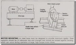
In the eve nt that the m otor must be mount ed on steel, all supports m ust be of adeq u ate size a nct strength an d braced to assure maxim umrigidity.
Wheth er the m otor base is concrete or steel, it mu st be level. If concrete, be sure it is not too h igh . A motor can always be rai sed by use of shims; but reduction of height by removal of some of the concrete surface would be diffi cult.
The requirement for a level base is critical. Usually, for a motol’ installa tion, there will he four points of mounting-one at each corner of the mounting base. Then there will he mounting requirements for the driven load. All mounting points must be on the exact same plane, or the equipment will not be level.
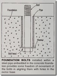
Before pouring the concrete founda tion, locate foundation holts by use of a template and provide secure anchorage (not rigid). It is recommended that a fabricated steel base be used between motor feet and foundation. See certi fied drawings of motor, base, and driv en unit for exact location of foundation bolts.
Mounting
For smaller motors, sliding bases and adapters are available for use with T-frame motors when they replace an old motor. Also, check whether other components or equipment, such as gears, special couplings, and pumps are to be mounted on the motor. If so, be sure space is available.
After the motor base is in place and before it is fastened, shim as required to level. Use spirit level (check two directions at 90°) to insure that motor feet will be in one plane (base not warped) when base bolts are tightened. Set motor on the base, install nuts, and tighten. Do not make a final tightening until after alignment. NEMA stan dards give dimensions of foot mount ings and some flange mountings. Expe r ience has shown that any base mounted assemblies of motor and driv en units temporarily aligned at the f actory, no matter how rugged or deep in section, may twist during shipment. Therefore, alignment must be checked after mounting.
Drives
Direct-connected motors with ball or roller bearings may be coupled to the load through flexible couplings. A cou pling should not be installed by ham mering or pressing. Always heat the coupl ing to install it on the shaft. Accurate mechanical lineup is essential for successful operation. Mechanical vibration and roughness during the operation of the motor may be indica tions of poor alignment. In general, using a straight-edge across and a feel er-gauge between coupling halves is not suffi cien t. It is recommended that the lineup be checked with a dial indi cator and checking bars connected to the motor and load machine shafts.
Sleeve bearings are supplied with a babbited face to restrain axial rotor movement during startup or while run ning disconn ected from the load. These babbited f aces are not intended to withstand con tinuous thrust loads, and care must be exercised in the lineup to prevent this from occurring during operation. Lineup should provide operation in the approximate mechanical
center between the extremes of end play; this is very close to the magnetic center location. Standard motors are supplied with more end-play. It is necessary that a limited end-float flexible coupling be used on sleeve-bearing motors to limit the total axial move ment to less than that shown in the motor outline drawings. As noted in NEMA Standard MG1-14.38, sufficient thrust to damage bearings may be transmitted to the motor bearing through a flexible coupling.
Ball-bearing motors, unlike sleeve bearing motors, should be coupled to provide more end-play in the coupling than in the motor. This is because ball bearings will take enough thrust, with out damage, to slip the coupling axially to accommodate thermal expansion in the system. The end-play of these motors may be as inuch as 50 to 150 mils, and the coupling should have at least this much float. Correct axial positioning can be obtained by tilting the motor toward the outboard end moving the rotor as far as it will go in that direction (the rotor will not be easy to move axially, since bearings must slide in the housing) or by bar ring the rotor over to the outboard end, and then positioning the motor to give at least 150 mils between the coupling halves or shaft ends. Or, the motor may be positioned without regard to rotor position so that coupling will allow 100 mils travel in either direc tion.
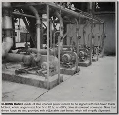
Belt drives require that the motor be mounted on slide rails or bedplate with provisions for adjusting the belt ten sion. Align the pulleys so that the belts run true (perpendicular to the shaft) and with uniform tension on all belts.
NEMA designations for motors
OPEN
General purpose. Ventilating openings permit passage of external cooling air over and around the windings of the machine.
Drip-proof. Ventilating openings are so constructed that successful operation is not interfered with when drops of liquid or solid particles strike or enter the enclosure at any angle from 0 to 15 deg downward from the vertical.
Splash-proof. Ventilating openings are so constructed that successful operation is not interfered with when drops of liquid or solid particles strike or enter the enclosure at any angle not greater than 100 deg downward from the vertical.
Guarded. Openings giving direct access to live or rotating parts (except smooth shafts) are limited as to size by the design of the structural parts or by screens, grills, expanded metal, etc., to prevent accidental contact with such parts.
Semi-guarded. Part of the ventilating openings, usually in top half, are guarded as in a “guarded machine,” but others are left open.
Drip-proof fully guarded: A drip-proof machine with ventilat
ing openings as in a “guarded” machine.
Externally ventilated. A machine ventilated by means of a separate motor-driven blower mounted on machine enclosure. Mechanical protection may be as defined above.
Pipe ventilated. Openings for admission of ventilating air are so arranged th<1t Inlet ducts or pipes can be connected to them.
Weather-protected. Type 1: Ventilation passage are so designed as to minimize entrance of rain, snow and airborne particles to the electrical parts. Type II: Ventilating passages at intake and discharge are so arranged that high-velocity air and airborne particles blown into the machine by storms or high winds can be discharged without entering the internal ventilat ing passages leading directly to the electrical parts.
ENCAPSULATED/SEALED
Encapsulated windings. An alternating-current, squirrel cage machine having random windings filled with an insulating resin that also forms a protective coating.
Sealed windings. An alternating-current, squirrel-cage rnachine making use of form-wound coils and having an insulation system which, through the use of materials, processes, or a combination of materials and processes, results in a sealing of the windings and connections against contaminants.
TOTALL V ENCLOSED
Nonventilated. Enclosure prevents free exchange of air between inside and outside of case, but not airtight, not equipped for cooling by external means.
Fan-cooled. Equipped for exterior cooling by means of a fan or fans, integral with machine, but external to the enclosing parts.
Fan-cooled guarded. All openings giving direct access to fan are limited in size by design of structural parts or by screens, grilles, expanded metal, etc., to prevent accidental contact with fan.
Explosion-proof. Designed and built to withstand an explo sion of gas or vapor within and to prevent ignition of gas or vapor surrounding machine by sparks, flashes, or explosions that may occur within machine casing.
Dust-ignition-proof. Designed and built to exclude ignit1ble amounts of dusts or amounts affecting performance or rating to prevent ignition of exterior dust on or in vicinity of enclo sure.
Waterproof. Designed to exclude water applied in a stream from a hose, except that leakage is permitted around the shaft, provided that water is excluded from oil reservoir and means of drainage is provided.
Pipe-ventilated. Openings so arranged that inlet and outlet ducts or pipes may be connected to them for the admissions and discharge of ventilating air.
Water-cooled. Cooled by circulating water; the water or water conductors came in direct contact with the machine parts.
Water-air-cooled. Cooled by circulating air which, in turn, iscooled by circulating water.
Air-to-air-cooled. Cooled by circulating internal air through heat exchanger which, in turn, is cooled by circulating external air.
See NEMA Standards MG 1-1.25, 26, 27 for additional details.
The slide rails should be located so that the motor is near the end of the slide rail closest to the driven machine. This permits maximum adjustment (travel) for belt tensioning and readjustment later to compensate for belt wear or belt stretch.
Tighten the belts just enough to prevent slippage at the rated horsepower. Excessive belt tension causes unneces sary loads on the shaft and bearings. On high-inertia loads or equipment that could jam or stall-where the belt squeal or slip during acceleration or where the torque approaches pull-out torque during overload or stall-tight ening to prevent this squeal or slippage will result in overloading the bearings or shaft. Belt speeds are normally lim ited to 5000 ft per min for E-section belts and 6500 ft per min for 8-V section belts. Speeds in excess of these limits should not be used without con sulting the belt manufacturer.
Gear drives require accurate align ment and rigid mounting. Pitch diame ter and width should not be outside recommended gear manufacturer’s limits. Check the factory for bearing thrust capacity before installing helical gears. In all cases, gear teeth must be centered with each other, correct shaft center distance must be attained, and gear faces must be parallel. Gear teeth must fully engage to a depth gi v ing approximately 0.002 in. minimum backlash; avoid engagement so deep that gears will deflect or bind. Test for proper alignment by rotating motor shaft by hand, checking driven gear for backlash through one complete revolu tion. Test backlash and face parallel ism again after tightening mounting bolts.
Mechanical alignment
With few exceptions, a flexible cou pling is used to connect the motor to the load. This type of coupling is designed to tolerate some misalign ment; however, this misalignment can cause vibration and/or stress on the motor bearings. Consequently, the shafts in all coupled applications should be lined up with the same high degree of accuracy, regardless of the type of coupling or type of bearing used. There are several important steps to follow in attaining correct alignment of direct-connected drives.
The foundation for the motor and driven load should provide a perma ment fixed relationship of the motor with respect to the driven load. The foundation should provide a solid anchor that will maintain this fixed relationship after alignment is com pleted.
Position the motor on its foundation to obtain the correct spacing between the motor shaft and the driven shaft. This distance is specified by the cou pling manufacturers and its usually in the range of 1/s to % in.
This positioning, in the case of sleeve-bearing motors, should limit the axial movement of the coupling to keep the motor bearing floating off of the thrust shoulders. These bearings will not take continuous thrust. When posi tioning the shaft of motors with end play, the shaft should be placed at the midpoint of the end play. (Ignore the magnetic center indication.)
Adjust the position of the motor by the use of jackscrews, shimming, etc., until the anglilar and parallel mis alignment between the two shafts is within the recommended limits as measured with a dial indicator with the motor bolted down. When adjusting the position of the motor, care should be taken to assure that each foot of the motor is shimmed, before the motor is bolted down, so that no more than a.002-in. feeler gage can be inserted in the shim pack.
Angular misalignment is the amount by which the faces of the two coupling halves are out of para llel. It may be determined by mounting a dial indicator on one coupling half with the indicator probe on the face of the other half, then rotating both shafts together through 360° to determine any varia tion in reading.
It is important, during this check, to keep the shaft of a motor with end-play against its thrust shoulder and the shaft of the driven load with end-play against its thrust shoulder to prevent false readings due to shaft movements in the axial direction.
Checkpoints for good motor support
1. No heavy welding should be done on machined bases after machining. If you see anything other than light tack welds on such a base, expect that some warpage has occurred.
2; Base welding-should be continuous. Intermittent welds allow twisting and distortion in many cases.
3. Box sections or tubes are much stiffer than channels or beams alone. But make sure box sections are not “split” or left open along one side; these lose much of their resistance to twisting.
4. A one-piece base under a drive is always better than a sectional base.
5. Deep bases are better than shallow ones.
6. Watch especially for twist and distortion caused by overhung loads in bases above floor or ground level.
7. Adjustable braces are usually out of adjustment.
8. Don’t take it for granted that the floor itself is solid. A solid-drive base on
a resonant floor can be just as shaky as a weak base on a rigid floor.
9. Vibration during operation is a trouble indicator, and very often the trouble is in the drive base. Look at base or alignment first, the motor itself last.
10. Make sure all hold-down bolts are in place, and are tight.
11. Check to see that all separable base joints are doweled- motor to-base, base-to-foundation beneath.
12. Watch for unshimmed gaps; all shims should be properly placed and in good condition.
13. Watch for stiffeners near attachment bolts. These greatly increase motor-base rigidity.
14. Look for bracing directly under the motor where it will do the most good;soleplates should be supported at least every 18 in.
Parallel misalignment is the offset
between the centerlines of the two shafts. It may be determined by mounting a dial indicator on one cou pling half with the indicator probe bearing radially on the other coupling half, then rotating both shafts together through 360°.
It is essential that the motor and load be correctly aligned under actual operating temperatures and conditions. Machines correctly aligned at room temperature may become badly mis aligned, due to deformation or differ ent thermal growth as they increase in temperature. The alignment must be checked and corrected if necessary after the motor and driven machine have reached their maximum tempera ture under load.
It is recommended that “floating shaft couplings” or “spacer couplings” be used on motors where the coupling alignment cannot be accurately check ed and/or maintained. Misalignments of several thousandths of an inch will result when there are relatively small changes in the temperature differences in larger motors and the equipment driven.
After alignment with the load, bolt the motor in pl ace with m aximum-size bolts. It is advisable to provide some variation in the location of the founda tion bolts. This can be done by locating the bolt s in steel pipe embedded in the foundation. It is recommended that a competent engin eer , familiar with mo tor foundation designs, be called upon to design and supervise foundations and support assemblies for large motors .
Next, the equipm ent should be given a test run to verify that the lineup gives satisf actory performance. Once satisfactory performa nce has been ver ified, th e m achin es should be doweled to their bedplates. Recomme nded dow eling is two dowels per machi ne, one in each of the diagonally opposite feet, with the size of the dowels approxi mat ely 1/z th e diameter of the hold down bolt s.
Machin es correctly aligned when they are first installed may subse quently becom e mi saligned due to wear, vibration, _shifting of the base, settling of the found ations, thermal expansion and contraction, or corro sion. Therefor e, it is advisab l e to recheck the alignmen t per iodically to correct for any changes.
Electrical connections
Article 430 of the NEC and NEMA standards provi de specific electrical and mechanical in stallation require ments and recomm end ations covering motors and motor controls.
Be sure that the voltage supply to the motor meets the motor require ments. Charact eri stics of the supply should correlate to the motor name plat e values as follows:
1. Voltage-within 10% above or below the value stamped on th e name plate.
2. Frequ ency-within 5% above or below the valu e stamped on the name plate.
3. Voltage and f requ ency together within 10% (providing frequency above is less than 5%) above or below values stamped on th e nam eplate.
After it has been ascertained that supply-voltage requirements are cor rect, the motor-t erminal conn ections should be mad e. Stator wi nding con nections should be mad e as shown on the nameplat e connection diagram or in accordance with th e wiring diagram attached to the insid e of the conduit box cover. Terminal connection prob lems are usually caused by the branch circuit conductors being a size that is different from that of the motor leads. Branch-circuit wire size is normally determined in accordance with the NEC based on the motor full-load cur rent, increased where required to limit voltage drop. The motor leads, on the other hand, are permitted a higher current-carrying capacity for a given A WG size than equivalent conductors used in branch-circuit wiring because they are exposed to circulating air within the motor.
When connecting the motor termi nals to the line leads, use connector lugs sized to the conductor. Lugs so chosen, however, may not connect to each other securely. There may be dif ficulties in matching the two sets of lugs so that the full surface area of the small terminal can contact that of the larger. Washers should never be used between the motor lugs and the branch-circuit lugs in an attempt to promote better contract.
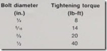
A higher degree of reliability is pos sible if connections are tightened accord ing to torque specifications. Proper terminations can be made up with a torque wrench. Recommended torques are as follows:
For wound-rotor motors, make connections to the rotor circuit in accord ance with the wiring diagram fur nished with the control apparatus. Also, conductors from the secondary control to the brushholder assembly must be installed and connected.
Brushes must make good contact with slip rings along the whole face of the brush. If needed, grind brushes in with fine sandpaper. Do not use lubri cants. Service ports are provided for inspection of slip rings and brushes. Spring pressure should be set at about 1 lb on 215-286T frames and 4 lbs on 324-449T frames.
Be sure the motor terminal box is of sufficient size to permit good, reliable connections. Over the years it has been revea led that the most frequent single complaint of those who work with motors is “the terminal box is too small.” In the 250- to 1000-hp range, particularly, the type and size of incoming cable determines how much room is needed. The designer is seldom given that information. The NEC is of no help because it offers so many options, such as the choice of copper or aluminum cable. In working more closely with the actual installation, the installer usually is in a better position to select the most appropriate box.
When mounting conditions permit, the motor terminal box may be turned so that entrance can be made upward, downward, or from either side. For oversize conduit boxes, such as those required for stress cones or surge protection equipment, the mounting height of the motor may have to be increased for accessibility.
It is recommended that the motor leads be supported and protected. They should be clamped at or near the point where they enter the box. A neoprene sheet “lead separator gasket” is help ful. This limits movement of cables under starting currents. Extra sleeving around leads in this area eliminates chafing or cutting of cable jackets. Holes in steel plates through which leads pass ought to be chamfered or at least deburred.
Big, heavy boxes need extra support from the motor frame or base. This is most likely with any box over 18 to 20 in. high, especially if it contains heavy accessories. When you start up large drives, watch the light reflected from flat terminal box surfaces. You may see a “shimmer,” indicating box vibra tion of fairly high amplitude, even when motor frame vibration is quite low. Such shaking may eventually
crack the box, break bolts, or damage the leads. When in doubt, brace it.
Identify motor auxiliary devices such as space heaters or temperature sen sors. Connect these in proper circuits and insulate from motor power cables.
Startup
After installation is completed, but before the motor is put into regular service, make an initial start as fol lows.
1. Check that the motor, starting,and control-device connections agree with wiring diagrams.
2. Be sure that voltage, phase, and frequency of line circuit (power supply) agree with the motor nameplate.
3. Check motor service records and tags accompanying the motor. Be cer tain bearings have been properly lubri cated and oil wells are filled.
4. Perform insulation-resistance tests. Before carrying out the test, the machine must be at a standstill, and all windings to be tested must be electrically connected to the frame and to ground for a time sufficien t to remove all residual electrostatic charge. Fail ure to observe these precaution s may result in inj ury to personn el. In accord ance with established standards, the recommended minim um insulat ion re sistance Rs for the stator winding is given by 1+ (V8/ 1000) wh ere Rs is in megoh ms at 40oC of the entire stator winding obtained by applying direct pote n tial to the entire winding f or one minute, and Vs is rated machine volt age. (See IEEE Reco mmend ed P rac tice for Testing Insu lation Resista nce of Rotating M achines, Publication No. 43, for more complete inf ormation.) If the insulation resistance is lower than this value, it is advisable to check for and eliminate moistu re in accordance with accepted procedures.
5. Be sure that the rotor turns f reely and does not rub when disconnected from the load. Any f oreign matter in the air gap should be removed.
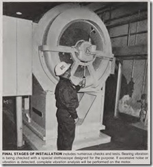
6. If the drive is disconnected, start the motor at no load long enough to be certain that no u nu sual condition exists. Listen and feel for excessive
noise, vibration, clicking, or pounding. If present, stop the motor immediately . Investigate the cause and correct before putting the motor in service.
5. Check direction or rotation. If incorrect , interchange any two line leads to reverse rotation on 3-phase motors. Fans on fan-cooled motors that have directional rotation name pla tes must be reversed on the shaft if rotation is changed.
6. If the drive cannot be disconnected, interrupt the starting cycle after the motor has accelerated to low speed. Carefully check for any unusual conditions as the motor coasts to a stop. Repeat several times if necessary; however , repeated starts can overheat the motor. Ref er to NEMA MG-1-20.42 and MG -1-20.43 or consult the factory for specific starting limitations to pre vent damage to motor.
When these checks are satisfacto ry, operate the motor at lowest load possible and look for any unusual con dition. Increase load slowly to maxi mum, checking unit for satisfactory operation . Then run at normal speed watching carefully for any abnormali ties.
10. Record all pertinent data, such as FL amps, volts, starting current (if an ammeter with the peak-current lock feature is available), insulation resist ance, noise level, and temperature, for future reference.
Hazardous locations
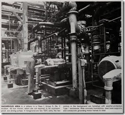
Motors suitable for use in hazardous locations are tested and listed by UL in its Hazardous Location Equipment Directory. These motors, which are supplied with a UL Class I, Group C or D, or Class II, Group E, F, or G label, have been designed and manufactured in accordance with standards estab lished by UL for explosionproof (ClassI) and dust-ignitionproof (Class II) machines. Parts are machined to very close tolerances, including conduit box and/or collector-ring access covers. Extreme care must be taken during disassembly and reassembly, since any nicks or burrs may destroy the explo sionproof or dust-ignitionproof fea tures of the machine. If these features are altered in any way the machine will no longer comply with the provisions of the UL inspection and label service manual and will no longer be properly classified as a UL-labeled motor. The label should therefore be removed and the motor considered unsafe for use in hazardous locations. Always consult the manufacturer or a listed apparatus repair firm to assure safe and proper assembly . Motors for use in hazardous locations must be marked with an iden tificatiQn number that indicates the operating temperature range.
To date, UL lists no motors for G roups A and B; hence where such conditions are encountered, motors must be located outside the hazardous area. Motors suitable for other Class I locations are designated as explosion proof.
Likewise, motors for use in Class III locations are not listed. Class III loca tions are those where there is presence of ignitible fibers or flyings, such as in textile mills and woodworking plants. However, totally enclosed nonventi lated motors and the so-called lint-free or self-cleaning textile squirrel-cage motors are commonly used. The latter may be acceptable to the local inspect in’g authority if only moderate amounts of flyings are likely to accumulate on or near the motor, which must be accessi ble for cleaning and maintenance.
